 | |||
|

| Home > Astronomy > ACAM > Imaging with ACAM |
Imaging with ACAM
ACAM delivers high-quality imaging
over a field of view ~ 8 arcmin in diameter.
Sections below:
The area imaged is a factor of 20 larger than that of ACAM's predecessor (the aux-port camera). The scale is approximately 0.25 arcsec/pixel (measured on-sky to be 0.253 in x, 0.254 in y, through an R-band filter). For sky PA = 0, north is right, east is up (as conventionally viewed). As the sky PA is increased, the direction of north will rotate away from that of east. I.e. for sky PA = 90, N is down, E is right. There is some vignetting at the left edge of the field. The illuminated area on the CCD is bounded by a square with approximate dimensions 44 < x < 2027, 946 < y < 2948. Most of ING's filters can be mounted in ACAM. A list of ACAM-compatible filters, and detailed information about each filter, can be obtained from the ING filter database.For convenience, the throughput curves for the new Sloan, old Sloan and Bessell sets of filters are reproduced on the ACAM filter transmissions page. A total of 11 filters can be installed in ACAM's two 7-position filter wheels at any one time (position 6 in wheel 2 is reserved for the VPH disperser, while position 7 in each wheel is clear). Unless observers request otherwise, ACAM's wheels usually contain a set of Sloan u g r i z filters (#700 - 704), manufactured by Asahi, which between them cover ~ 3300 - 10000 A. These Sloan filters, commissioned in 2011, are larger (60 mm diameter) than the old 50-mm Sloan g r i filters (#219, 216, 217), reducing the risk of vignetting (the filter wheels are located at a near-pupil). They also have slightly better throughput than the old Sloan filters. The old Sloan filters are still available if required.
Overview of ING filter sets
The filter dimensions (columns 3 and 4) and approximate bandpasses (column 6) are taken from the ING filter database. A single number for the diameter indicates a circular filter. The filters mounted in the MAINFILTC and MAINFILTND slides in the WHT's Cassegrain acquisition and guiding box can not be used with ACAM - they lie physically below the light path to ACAM. Observers who would like to bring their own filters to use in ACAM, should contact ING to check that the filters will fit in the instrument, that suitable mounts are available, and that the filters will deliver a good PSF when used in ACAM. Observers interested in borrowing filters from the collection at the Nordic Optical Telescope should seek permission from NOT staff, well in advance of the observing run.
Mounting the filters
50-mm square or circular filters can be mounted in either wheel, but wheel 2 is preferred. The bundle of rays from the whole field has diameter 42 mm at wheel 2, but 51 mm at wheel 1, so there's a risk of vignetting (of the light from all objects in the field, and particularly those near the edge of the field) if the filter is mounted in wheel 1. If several non-Sloan filters are required in the filter wheels, the support astronomer should be informed at least a few weeks before the run, so that e.g. the availability of suitable filter adaptors can be confirmed. An adaptor is available to mount in the focal-plane slide any filter which can be mounted in the filter wheels. In addition, several adaptors are available to mount 106-mm filters in this slide. The slide has only two slots for filters and, as with the filter wheels, one position is usually left empty, to allow observing with filters or grisms in the main wheels during the same night. The INT WFC filters are too large (139 mm) to use in ACAM.
Transmitted wavefront errors - effect on PSF
For narrow-band imaging at the wavelength of the Hα line (zero redshift, or redshifted), the TAURUS filters have better TWE (but smaller bandpasses) than the old 50-mm square Hα filters (names starting 'H...'). For narrow-band imaging at other wavelengths, both the TAURUS filters and the old 50-mm square filters have acceptable TWE. If you're planning to use a filter with large or unknown TWE, please contact Chris Benn (crb@ing.iac.es) or Lilian Dominguez (ldp@ing.iac.es) in advance, and we'll arrange for the filter to be tested on-sky.
Focus offsets
Shifts introduced on inserting filters
Throughput
Relative popularity of filters
The most-used narrow-band filters are those of the 50-mm Hα set, and the TAURUS filters covering a similar wavelength range. For both sets of filters, frequency of use (over 2009 - 2014) declines with wavelength shift Δλ redward of Hα, approximately as (1 + (Δλ / 50 A))-1, i.e. approximately as (1 + (velocity / 2300 km/s))-1. Narrow-band filters can be mounted in the focal-plane filter slide (maximum 1 filter, usually) or in the pupil-plane filter wheels (maximum 11 filters in two wheels).For the focal-plane slide, we have one adaptor which will take filters of diameter <= 76 mm, and 3 adaptors for the private 106-mm Andover filters. There are only two empty slots in the focal-plane slide - if both are occupied by filters, it will not be possible to take images through any of the filters in the pupil-plane filter wheels. The pros and cons of using filters in the focal-plane slide and the pupil-plane wheels are summarised below. All broad-band observers, and most narrow-band observers, use filters mounted in the pupil-plane wheels. Note the comments above about the effect of transmitted wavefront errors on delivered PSF. NB the quoted central wavelengths of the 50-mm narrow-band ING filters (but probably not the TAURUS narrow-band filters) refer to use in an f/4.5 beam (ING Observers' Guide, appendix D.1.4.1).
Use in focal-plane filter slide
The largest filters which can be accommodated in the focal plane have diameter 106 mm, corresponding to a 7-arcmin field of view. 76-mm and 50-mm filters will deliver fields of view 5 and 3 arcmin in diameter respectively. In the focal-plane slide, the filter will be in the f/ll converging beam, so the central wavelength of interference filters will be shifted ~ 0.8 A to the blue relative to the quoted central wavelength, but the shift does not depend on the radius in the field of view. Observers may prefer to use the focal-plane filter slide if they are imaging objects subtending large angular size, through narrow-band filters. Otherwise, they will probably want to use filters mounted in one of the pupil-plane wheels.
Use in pupil-plane filter wheel
The bundle of rays in the near-collimated beam has diameter 51-mm at the position of filter wheel 2, so even ING's 50-mm filters will barely vignette the field if mounted in this filter wheel. For narrow-band filters placed in the pupil-plane filter wheels, there will be a shift in wavelength which rises ~ as the square of radius in the field, and is inversely proportional to the square of the refractive index (which is likely to lie between 1.5 and 2). For a filter with effective refractive index 1.5, at radii 2 and 4 arcmin, the shifts to the blue are ~ 6 and 20 A respectively. For refractive index 2.0, the shifts are ~ 3.5 and 12 A at these two radii.
Tweaking the central wavelength
Filters in the focal-plane can be tilted, at the time of installing the filter in the slide, by any amount up to 10 deg, with rms accuracy 0.5 deg. In the pupil-plane wheels, plastic wedges (currently still being commissioned, as of February 2014) can be inserted to tilt the filters by 3.5, 5, 7 or 10 deg, with accuracy ~ 1 deg. Space constraints preclude tilting in the pupil-plane wheels of filters with diameters > 76 mm (should mounts ever be made for these). Tilting a filter will also broaden the bandpass to the blue, and the peak throughput will drop correspondingly (see ING Observers' Guide Section D1.7.) For a filter in a collimated beam (i.e. in the filter wheels), the fractional bandwidth does not change (so for a change in central wavelength ~ 5 A, the change in bandwidth is << 1 A). For a filter in a converging beam (i.e. in the ACAM focal plane), the change in bandwidth is larger (contact the ACAM instrument specialist for more information).
Change of central wavelength with temperature
ACAM was designed to deliver high-quality images, in any wavelength band U through Z, over as large a field of view as possible, although of course no design with a small number of optical elements can deliver perfect PSF at all radii. When ACAM is used to image a pinhole in the focal plane, the delivered FWHM in U B V R I and Z bands are: Radius FWHM arcmin arcsec 0 < 0.25 (too small to measure) 3 < 0.4 4 0.6 (some coma)In practice, this means that ACAM is unlikely to significantly degrade the natural seeing (rarely better than 0.5 arcsec) in the central 6-arcmin diameter field. (The PSF delivered by the telescope optics alone at the f/11 folded-Cass focus is smaller: FWHM ~ 0.25 arcsec on-axis, mostly coma and astigmatism, rising to ~ 0.35 arcsec at a radius of 5 arcmin.) The following 10-sec R-band exposure of M53, obtained by Samantha Rix on 29 March 2010:
has circularly symmetric PSFs, with FWHM 0.65 arcsec, across the whole field of view, and there is no degradation in the observed PSF at the edge of the field of view. The symmetry of the on-axis out-of-focus R-band star image below provides additional confirmation that the ACAM optics introduce no aberrations at a level of several tenths of an arcsec:
The predicted throughputs of the telescope, A&G flat, ACAM optics (excluding filters) and CCD, are given below for each waveband.
Band               U     B     V     R     I     Z

C. wavelength A   3600  4300  5500  6500  8200  9500    (typical values)

WHT M1 + M2       .73   .73   .73   .73   .73   .73     = 0.85^2, typical

A&G flat          .80   .90   .97   .97   .97   .97     (overcoated silver)

ACAM optics       .65   .71   .73   .73   .72   .72

AUXCAM QE         .35   .55   .85   .90   .80   .30     from QE curve
                                                        on web page
                  ---   ---   ---   ---   ---   ---
Total             .13   .26   .44   .47   .41   .15
The properties of the AUXCAM CCD (high QE, very low fringing) are similar to those of the REDPLUS CCD used on the red arm of ISIS.
Measured zeropoints
(Effective bandwidth is defined as the integral of T(w)dw, where T(w) is the transmission of the filter and w is the wavelength, i.e. the area under the filter transmission curve.)
Throughput relative to that of the WHT PF camera
i.e. ACAM outperforms WHT PF in the red, and under-performs it in the blue, largely because of the different shapes of the CCD QE curves. (The larger number of mirror and lens surfaces in the light path to ACAM's CCD is to some extent compensated by its overall higher QE.) In-focus ghostsWhen used in wheels 1 and 2, some filters may introduce faint in-focus ghosts. So far, this has been seen only when the old Sloan r filter (#216) is deployed, with each bright star being accompanied by an in-focus ghost ~ 8 arcsec away, at a level ~ 0.1% (i.e. ~ 7.5 mag fainter):
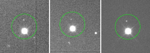
In each of these images (two of bright stars, one of an asteroid, taken 2010 Dec 26 by Ovidiu Vaduvescu), a ghost can be seen above the main image of the bright object (the green circle encompasses both). The ghosting is likely to be caused by a double reflection within a filter with slightly non-parallel sides. The predicted brightness of the ghost would then be ~ 4% * 4% = 0.16%, which is consistent with the brightness of the observed ghost. It should be possible to displace the ghosts further from the main images once the 'filter tilter' mounts are commissioned (expected 2012).
Out-of-focus ghosts
In the above image, the 3 ghost images are all out of focus, and are spread along a line through the star image (right of centre) and the optical axis of the camera. The integrated intensity of the light in these ghosts is about 2% that in the main image of the star (the latter inferred from an unsaturated image). Both the form and the intensity of the ghosts are consistent with expectations from Zemax modelling (by Tibor Agocs) of ghosting in ACAM: 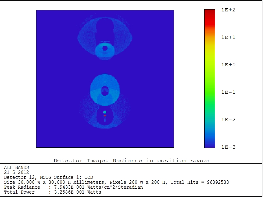
Ghosts might also be caused by use in wheels 1 and 2 of filters introducing large wavefront aberrations but so far we've seen evidence of this for only the old Sloan r filter (#216, see above). The image below (taken by Dan Perley in July 2018) shows ghosting of a bright star near the edge of the field of view (click for enlarged view): 
Light-leaks
Support astronomers should refer to the filter-change notes for guidance on masking the edges of filters.
Scattered moonlight At angles of less than 4 deg, or between 20 and 26 deg, there is no scattered light, because the telescope structure blocks moonlight from reaching the baffle. At angles larger than 26 deg, there is some scattered light, but fainter than moonlit sky. Observers are advised to take a test image before observing, to check whether scattered light is present. In some circumstances, it may be helpful to block the moonlight by lowering or raising the dome shutters (consult with the telescope operator). The scattered moonlight typically manifests itself as a broad bright feature covering most of one half of the imaging area, and with intensity a factor 2 - 3 times higher than that on the uncontaminated imaging area (i.e. moonlit sky):
The scattered light is in the bottom/top half of the CCD when the elevation of the telescope is higher/lower than that of the moon, and is on the right/left side of the CCD when the azimuth of the telescope is less than / greater than that of the moon. During 2009 - 2011, the light path has been experimentally baffled at various points along the light path from the Nasmyth turret to the ACAM filter wheels, and in late 2011, the intensity of the scattered light was reduced by a factor ~ 3, after introducing a series of annular baffles ('Chinese lantern' baffle) in the below-Nasmyth turret above the WHT's primary mirror. Nevertheless, scattered light remains a problem and is still under investigation. The scale at the CCD has been measured on-sky, through an R filter, at 24 points sampling the full field of view.The median scale is 0.2530 arcsec/pixel in x, and 0.2538 arcsec/pixel in y. It varies slowly (on scales ~ arcmin) across the CCD, with rms variations ~ 0.2% in both x and y directions. There appears to be no systematic radial distortion (e.g. 'pin-cushioning') at this level. Flexure is discussed on the spectroscopy pages. For most imaging observations, bias frames, sky flats and standard-star observations will be required.
Flat fields - when to take them
The telescope operator can advise about blank fields. A catalogue of such fields is loaded into the telescope control system on startup, and more are listed on the INT WFC blank-fields page.
Flat fields - radially-symmetric gradient
This feature is seen in both sky and dome flats (typically 1 - 10 sec exposures) and in longer exposures on the moonless night sky (100s sec) and is probably due to off-axis light being scattered into ACAM (see Section 6 above for a discussion of scattered light). The gradient is not due to any of: vignetting increasing with radius in the field of view; change of scale across the field ('pincushion' distortion); or finite time taken to open and close the shutter.
Flat fields - cosmetics
Most of these features flat-field out. They are discussed in more detail on the ACAM CCD page. The features are mainly artefacts of CCD manufacture, but some of the dark patches might be due to dust particles on the CCD surface or on the cryostat window (neither of which can easily be cleaned). ACAM does not have an atmospheric-dispersion corrector, so observations in the blue should be carried out at high elevation if image quality is critical (the same was true of ACAM's predecessor, the aux-port camera), although at low elevation the seeing is likely to be poorer anyway.At a zenith distance of 30 deg, atmospheric dispersion will stretch an image obtained through typical U, B, V and R filters by 0.33, 0.37, 0.19 and 0.12 arcsec respectively. At zenith distance 50, the equvalent numbers are 0.7, 0.7, 0.4 and 0.2 arcsec, and at zenith distance 60, the numbers are 1.0, 0.9, 0.6 and 0.45 arcsec. |
| Top | Back |
|
