 | |||
|

| Home > Astronomy > ACAM > ACAM observing guide |
ACAM observing guide
1. Introduction
See the imaging and spectroscopy pages for a description of the science capability and performance. This page provides a step-by-step guide to actually observing with ACAM. A summary of the control commands (and syntax) can be found on ACAM's observing commands page.
Click on the image for a larger version. 2. Before arriving at ING
PIs should make sure that their filter requirements are known well in advance. See the ACAM imaging page for a description of what filters/sets are available, and the options for mounting them in ACAM. If you have several targets, it's useful to create a target list in the standard format (e.g. Q1834+22 18 34 11.43 22 16 07.2 j2000) read by the telescope control system. The target list can be emailed to the support astronomer for upload into the control system (in /wht/cat) before you arrive. 3 - Afternoon/evening
During the afternoon of the first night of the run, ING's operations team will carry out basic checks of ACAM, including making sure that the system is sensitive to light. The support astronomer will be present during the afternoon/evening of the first night of your run. He/she will mount in the filter wheels the filters you have requested. The filters in the wheel can't be changed during the run, unless this was specified in the original observing proposal (in particular, such changes are not usually possible during the night). If there's time during the afternoon, take bias frames, and W flats and an arc for spectroscopy (see the imaging and spectroscopy sections below for instructions). 4 - User interface, observing commands
Control of ACAM is straightforward. The observing commands described below can also be found on the observing commands summary page. In light-path order (in the direction left to right on the figure at the head of this page), the following are under user control:
Most of the above can be controlled by typing commands at the instrument-control screen (pink window, the prompt is usually TO>). The mechanisms can also (and more conveniently) be controlled from the ACAM instrument-control gui, the top half of which includes pull-down menus showing the ACAM options available.
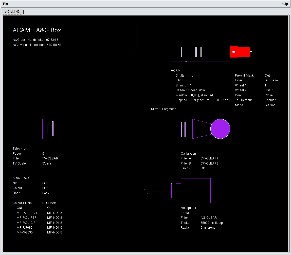
The status of ACAM and of the Cassegrain A&G box is shown on the ACAM graphical mimic:
Detector status is shown on the CCD-status window:
Click on the images above for larger versions.
4.1 - A&G fold flat
TO> agacam (which is an abbreviation for agmirror largefeed). agacam automatically switches off any calibration lamps which are currently switched on. To allow ACAM to view light from the standard calibration lamps in the A&G box, type TO> acamcal (which is an abbreviation for agmirror smallfeed or agacamcal). The switch between viewing sky (agacam) and calibration lamps (acamcal) now takes only 20 sec (formerly ~ 55 sec, prior to conversion of the A&G-box control to a PLC-based system in June 2010).
4.2 - A&G calibration lamps
TO> complamps cuar for the CuAr arc lamp (NB this lamp may not be available if LIRIS is mounted at the Cassegrain focus of the WHT). The other options are: TO> complamps cune (CuNe arc lamp) TO> complamps cuar+cune (both arc lamps) TO> complamps w (tungsten continuum lamp)
TO> complamps off (lamps off)
To insert neutral density filters in the light path (within the calibration unit), type e.g. TO> compnd 2 to insert filters with total neutral density ~ 2 (i.e. a factor of 100). The complamps and compnd commands are prone to timeouts, in which case the command may need to be repeated.
4.3 - Slit-mask slide
TO> acamslit -p 2 or TO> acamslit ACAM_0.5 to drive the slide to position 2. When the slide is moved to any of positions 2 - 7, a pre-slit mask also slides into position on-axis, just before the slit in the light path. This allows light to pass only through the selected (now on-axis) slit and prevents any light passing through the other slits in the mask.
4.4 - Filter wheels 1 and 2
TO> acamwh1 4 (moves wheel 1 to position 4) or TO> acamwh2 SlnR (selects the Sloan r filter in wheel 2). I.e. the positions can be selected by either name or number, as for the slit slide.
4.5 - Configuring ACAM
E.g. to configure ACAM for imaging through the Sloan u filter: TO> acamimage SlnU Optionally, a slit can also be moved into the light path (useful during acquisition of spectroscopic targets), by specifying as a second parameter the slit width, e.g. 1 arcsec: TO> acamimage SlnR 1 To configure ACAM for spectroscopy with the 1-arcsec slit and the V400 grism: TO> acamspec V400 1 Optionally a filter can also be deployed, by specifying its name as a third parameter e.g.: TO> acamspec V400 1 SlnR or to include the GG495A second-order-blocking filter in the light path: TO> acamspec V400 1 GG495A
4.6 - CCD setup
Window/s
TO> window acam 1 "[1:2148,800:3300]" Up to three other windows can also be defined. E.g. a smaller window can be useful when focusing the telescope, which requires the readout and analysis of many short exposures. To enable such a window: TO> window acam 1 disable (to avoid having overlapping windows active simultaneously), then e.g.:
TO> window acam 2 "[950:1150,1050:1250]"
To enable a currently-disabled window 1: TO> window acam 1 enable but make sure that any overlapping windows are disabled first. If frequent switches between defined windows are required (e.g. during setup), it's helpful to define a script to do this, e.g. ~/scripts/acam/acamw1 and acamw2 switch from window 2 to 1, and vice versa. To call the script from the home directory, type e.g. TO> scripts/acamw1
Binning
TO> bin acam 2 2 will set the binning to 2 in each of the x and y directions (in specroscopy mode, dispersion is in the y direction).
Readout speed
TO> rspeed acam fast The options are fast or slow. See Appendix 2 at the end of this page for example CCD readout times as a function of readout window, binning and readout speed.
DAS reset
TO> dasreset acam This takes ~ 30 sec to run. Afterwards, check the window, binning and speed settings.
4.7 - Data-acquisition
4.8 - Further information
5 - Focusing the telescope for imaging
If an observation with ACAM is required at short notice, it's helpful to know the approximate focus offsets from best focus for ISIS and LIRIS. These are usually ~ +0.27 mm and ~ -0.08 mm respectively (the latter for ACAM with the Sloan-g2 filter relative to LIRIS with the jc filter, measured 18/3/11). The telescope is focused by moving the secondary mirror, along the telescope axis, to minimise the FWHM of star images on the ACAM CCD. (Focusing the telescope for spectroscopy with ACAM is dealt with in Section 7.4.) If switching between ACAM and another instrument (e.g. ISIS) during the night, keep an eye on the telescope focus offset being applied (see Section 5.4).
5.1 - Doing a focus run
Insert the required filter in the light path. If several filters will be used, it's probably best to focus through a red filter (better seeing than through a blue filter) e.g.: TO> acamimage SlnR or, e.g. if this filter is mounted in position 5 of filter wheel 1: TO> acamwh1 5 To focus, step through a series of (>~ 7) focus values centred on 98.10, initially in intervals of 0.05 mm, and find the value which gives minimum FWHM on the iraf-displayed image. The focusrun command can be used to obtain the images, e.g.: TO> focusrun acam 9 7 97.9 0.05 takes 9 exposures of 7 sec each, initial focus = 97.90 mm, focus step = 0.05 mm. To adequately sample the seeing, exposure times should not be less than ~ 7 sec.
5.2 - Analysing the data from the focus run
(1) The bestfocus script (written by Inaki Ordonez, and currently, October 2015, being commissioned) can be run with: iraf> !python /home/whtobs/acam/bestfocus.py The script asks for the name of the first image of the run (the images must have consecutive run numbers, as generated e.g. by focusrun) and prompts the user to mark a few suitable stars on an image (saturated stars and artefacts are rejected). The script then plots measured FWHM vs telescope focus (blue) and a fitted parabola (red):
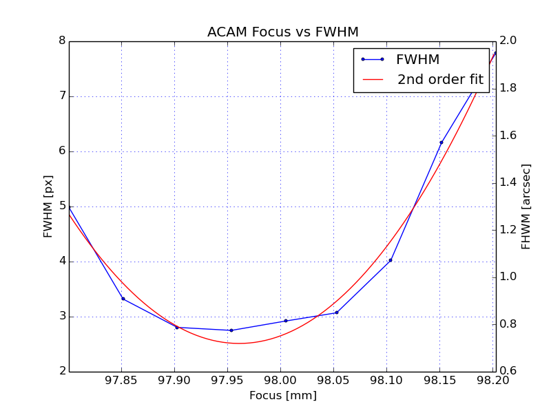
and reports the best-fit telescope focus (minimum of fitted parabola) and best empirical focus (focus of image which had minimum FWHM), both 97.96 in the above example. NB when running script, ignore any warning about 'AstropyDeprecation'. (2) Manual analysis of the focus-run data, by measuring the FWHM of the stars on each image using iraf imexam:
If the seeing is good (< 1 arcsec), it's worth focusing with accuracy ~ 0.02 mm (which correponds to 0.16 arcsec diameter at the f/11 focal plane). For fine-tuning the focus, you may want to iterate manually, rather than use focusrun:
Defocus broadens an image obtained at the f/11 Cassegrain focus of the WHT by 8.2 arcsec (33 ACAM pixels) per mm of secondary movement. E.g. 0.8 mm of defocus (~ 26 pixels) looks like this:
5.3 - Focus offsets
By default, when the ACAM control system is started up, it enables automatic application of known focus offsets relative to that for Sloan r (#702), for filters mounted in the filter wheels, e.g. at the time of writing the offset used for Sloan g is 0.08 mm. The offset for each filter is taken from the ING filter database, and is displayed on the ACAM control gui (in grey characters, but this does not mean that the offset is not active). The relevant focus offset will be applied whenever a filter is moved into the light path, and the value of this offset will be reported (as 'df') on the telescope-control information panel. The automatic focus offsets can be disabled with: acam_focus disabled and re-enabled with: acam_focus enabled New offsets can be entered by the observer at the ACAM control gui (click on the 'Edit' button) and are copied into the ING filter database, for use whenever they are next required (the old values are over-written, although there are some reference values stored in the filter database). The focus offsets between filters depend mainly on filter bandpass and thickness, and are discussed on the ACAM filter focus offsets page. For convenience, we note here, for the new Sloan filters (#700 - 704), the predicted offsets in focus in mm (all relative to Sloan r #702), and the median focus offsets (and rms error) deduced from focus runs so far (as of April 2012):
In the unlikely event of requiring more than one filter in the optical path at a time, the automatic focus offsets should be disabled, otherwise the observing system will apply the sum of the individual filter focus offsets. There are no automatic focus offsets when switching to (or between) filters mounted in the focal-plane slide (as opposed to the filter wheels). The focus must be determined on-sky as above, and must thereafter be set manually with the focus command e.g.:
5.4 - Focus-offset changes when switching between ACAM and other instruments
The safest way of switching is for the telescope operator to use the INSTRUMENT command (in the TCS control window). The INSTRUMENT command sets df to zero. So if the requested instrument is ACAM, it's then necessary to change or confirm the filter, e.g. with: acamimage SlnR 1 to make sure that the correct df for the filter is applied. Occasionally, when switching to ISIS to take an observation of a bright star, and when guiding is not needed and time is short, the INSTRUMENT command is not used, in which case the df is unchanged, and will usually be non-zero and wrong. One workaround here is to first set each ACAM wheel, and the ACAM focal-plane slide, to a position with no filter, and hence df = 0, suitable for ISIS. 6 - Imaging
6.1 - Setting up the CCD
The vignetting at the left edge is due to a small mis-positioning of the CCD in its cryostat. At sky position angle 0, north is right, east is up. The useful imaging area (+ overscan at left edge) occupies approximately 1 < x < 2030, 940 < y < 2950. The scale is 0.25 arcsec/pixel. If both imaging and spectroscopy are to be used, it's better to window the CCD so as to include the useful area for spectroscopy as well, using: TO> window acam 1 "[1:2148,800:3300]" Most observers will not need binning (the scale is 0.25 arcsec/pixel), but it can be implemented with e.g.: TO> bin acam 2 2 to bin x2 in each direction. To change the readout speed: TO> rspeed acam slow or 6.2 - Biases, sky flats, dome flats
Bias frames
TO> bias acam or TO> multbias acam nn
Note that the overscan strips lie at x < 50 and x > 2048. Observers using small windows for their science targets (to minimise readout overheads) may want to define additional windows to sample the overscan strip, see Appendix 2 for impact on readout overhead. ACAM biases should not be obtained simultaneously with biases on ISIS - this results in horizontal features on both sets of biases.
Sky flats, autoflat
Suggested sky-flat exposure times can be found in Appendix 4. A script autoflat is available for obtaining several sky flats though each of a specified set of filters. To run the script, set the CCD readout speed, binning and windowing (window 1 only - the script will not work for other windows) as required for the science exposures, then: cd /home/whtobs/acam/jmcc/under_development/autoflat Then e.g.: python autoflat.py acam 4 SlnG SlnR SlnZ to obtain 4 flats, through each of the Sloan g, r and z filters. autoflat aims to deliver for each flat between 20k and 40k counts per pixel. It takes test exposures (using a small window, in fast readout mode) to monitor the sky brightness and sets exposure times (min and max 1 and 120 sec) accordingly, working through the filters in an appropriate order (i.e. not necessarily that supplied by the user). There is automatic dithering between exposures. If the script fails part way through, take the rest of the sky flats manually. The autoflat script was provided by James McCormac.
Dome flats
6.3 - Target acquisition
Ask the telescope operator to slew the telescope to the target. At sky PA = 0, N is right and E is up on the images. At sky PA = 270, N is up and E is left. The target usually appears within a few arcsec of the rotator centre, which lies near x, y = 1098, 1890 (10/2009) on the unwindowed CCD. If required, the operator will look for a guide star. Check that the slit slide and filter wheels are in the correct position (usually two of them will be clear, one will have a filter in the beam). Take a test glance exposure, check the image against the finding chart: TO> glance acam 10 & Then check that the telescope is autoguiding, and take the science exposure, e.g. TO> run acam 900 & or a series of science exposures, e.g.: TO> multrun acam 3 900 & will take 3 900-sec exposures (if dithering is required between individual exposures, use the multdither command). 7 - Spectroscopy
7.1 - Setting up the CCD
The CCD window used above (outer boundary of the figure) has 1 < x < 2148, 800 < y < 3300, and can be set with: TO> window acam 1 "[1:2148,800:3300]" This is big enough to include the whole useful wavelength range in y, and also the whole 8-arcmin field of view in imaging mode. In the spatial direction, the spectrum runs from x = 335 - 1725, corresponding to a slit length ~ 5.8 arcmin. Red is at the top, blue is at the bottom. A rough equivalence between y pixel value and wavelength is given on the ACAM spectrocopy page. For the wavelengths of prominent arc lines, see the ACAM CuAr and CuNe arc maps. For spectroscopic programmes not requiring science imaging, a smaller window could be used e.g.: TO> window acam 2 "[665:1385,800:3300]" In imaging mode (for acquisition onto the slit) this still gives a field of view of 3 armcmin x 8 arcmin, sufficient to identify the field. NB if a measurement of the mean bias level during each exposure is needed, extend the window to the left edge (ideally) of the CCD (to include the bias strip, 1 < x < 50). For slit widths >~ 1 arcsec (spectroscopic resolution >~ 4 pixels on the CCD), the CCD can be binned, to reduce readout noise and readout overheads, e.g.: TO> bin acam 1 2 The spatial scale on the CCD is 0.25 arcsec/pixel, as in imaging mode, so it may also be useful to bin in the spatial direction, depending on the seeing and the angular diameter of the target, e.g.: TO> bin acam 2 2 With this binning, and the window size specified in the previous paragraph, the dead-time between consecutive exposures is only 5 sec. The readout noise per unbinned pixel is ~ 3 electrons in slow readout mode, 6 in fast. Set the speed with e.g. 7.2 - Rotation / curvature on the CCD Arc lines: the central ~ 1 arcmin of the arc lines (slit images) is rotated relative to the CCD rows by only ~ 0.1 deg (clockwise). (From June 2009 until adjustment of the cryostat in late 2010, the rotation was larger, ~ 0.7 deg clockwise.) The arc lines are also curved (as can be seen by clicking on the above figure for an enlargement), with the y value at the centre of the line being slightly higher than the mean of the y values at the left (2.5 pixels lower) and right (4.5 pixels lower) ends of the line. The curvature arises as a result of the VPH (and its flanking prisms) being in an f/22 beam, rather than a collimated beam. Spectrum: the spectrum is rotated anti-clockwise relative to the CCD columns, by about 2.0 deg.
7.3 - Biases, spectroscopic configuration, flatfields and arcs
7.3.1 - Bias frames
TO> bias acam
Note that the overscan strips lie at x < 50 and x > 2048. ACAM biases should not be obtained simultaneously with biases on ISIS - this results in horizontal features on both sets of biases.
7.3.2 - Spectroscopic flats
TO> acamcal TO> complamps w TO> compnd 1.5 Then select the desired slit width and the VPH grating in the filter wheel, with e.g.: TO> acamspec V400 1 (NB not acamspec V400 1.0, see the ACAM commands glossary) or TO> acamspec V400 0.5 or, to include the GG495A order-blocking filter in the light path: TO> acamspec V400 0.5 GG495A equivalent to: TO> acamslit ACAM_0.5 then, if the GG495 filter is in position 6 of wheel 2: TO> acamwh2 6
Then expose the flat-field images, with:
Then switch off the lamps, remove the ND: TO> complamps off TO> compnd 0 Troubleshooting: if your flat-field looks more like a light leak than a flat-field, check that the A&G mirror is in the correct position (i.e. acamcal, not agcomp!).
7.3.3 - Arcs
These lamps provide only weak lines in the blue, so two exposures are needed - a short one for the red end of the spectrum, and a longer on for the blue (no ND filter is required) e.g. for a 1-arcsec slit: TO> acamcal (if not already deployed) TO> complamps cuar+cune TO> arc acam 1 TO> arc acam 15 TO> complamps off ACAM flexes significantly as the telescope elevation and rotator position angle change. For accurate wavelength calibration, arc exposures should be taken before or after observing each science target.
7.4 - Focusing the telescope
The net telescope focus is actually the sum of this value (and an automatic correction for temperature) and the filter focus offset df. df is shown on the ACAM mimic display, in the entry for the VPH, and is usually set to -0.16 (mm). When the VPH is in the light path, this value is also shown on the TCS information display (bottom line, to the right of the nominal telescope focus value). In principle, the nominal focus offsets df (df = 0 for the Sloan r filter, by convention) take care of the change in telescope focus required when changing between filters or between filter and VPH. In practice, the measured df for spectroscopy has in the past been found to range from -0.11 to -0.22 (perhaps because of flexure in ACAM), and if carrying out both imaging and spectroscopy, it's a good idea to check the focus for both (and tweak the focus offest for the VPH accordingly). An error in applied focus of 0.05 mm corresponds to a defocus in the focal plane of about 0.5 arcsec. If switching between ACAM and another WHT instrument during the night (or day), please note the advice under Section 5.4 above about the risk of inheriting the focus offset of the wrong instrument.
7.5 - Target acquisition
Acquisition is normally carried out by the telescope operator, using the ACAM acquisition tool.
The image above shows a star acquired onto the centre of a slit (no disperser in the light path). If the target is very faint, a blind-offset star will be required. Experience suggests that, to minimise acquisition overheads, a blind-offset star should be provided if the time taken to image a star-like target with S:N ~ 30 is > 3 sec. This translates, for 1-arcsec seeing, into magnitude limits R ~ 19.5 / 19.2 / 18.6 (for dark / grey / bright of moon), and for 1.5-arcsec seeing, R ~ 19.2 / 18.8 / 18.2 (for dark / grey / bright).
7.6 - Scripts
TO> acam/spec Warning! These scripts send several offset values to the telescope-control system (TCS) in quick succession, and occasionally cause communication with the TCS to hang, which can be solved only by restarting the observing system (allow ~ 10 mins for this). This is under investigation.
7.7 Data reduction and quick-look
7.7.1 Quick-look spectrum extraction
ecl> acam
ecl> acam_ql and respond to the prompts, or give required parameters on the command line, e.g.: ecl> acam_ql r1234567 985 extracts from r1234567.fit a spectrum near x = 985 on the CCD. Additional parameters can be specified on the command line, e.g.: ecl> acam_ql r1234567 985 s f y
's' indicates a stellar object (alternatively 'e' for extended). 'f' indicates a faint object (alternatively 'b' for bright - triggering a different optimal extraction). The final parameter on the line indicates whether or not the extracted spectrum is to be kept ('y' for yes or 'n' for 'o'). The names of the data, destination and scratch directories used can be changed using iraf's epar. If acam_ql fails to find the named file, it will report to the user the name of the directory in which it is looking. The script extracts the spectrum, calibrates approximately in wavelength and intensity (using archival calibration data), and displays it in an iraf graphics window using splot (all the usual keystrokes available). Hit 'q' to exit from the plot and be offered the option of saving the spectrum.
Above is an example output from acam_ql. It shows an ACAM spectrum of a broad-absorption-line quasar at redshift 3.06. The prominent broad emission lines at wavelengths ~ 5000 - 6300 A are Lyα/NV, SiIV and CIV. The broad absorption lines just blueward of CIV (also visible in OVI, NV and SiIV) are due to ionised outflows with speeds up to ~ 15000 km/s. Features due to the earth's atmosphere at 5577 A (remnant of a sky line) and at ~ 7600 A (A-band absorption) provide a helpful check of the wavelength calibration. acam_ql was developed by Javier Méndez, October 2012.
7.7.2 Alignment of sky lines with CCD rows
Until 2010 November, the rotation required (for binning 1 x 1 or 2 x 2) was 0.66 deg, but is now much less (following rotation of the CCD on its mount). This can be corrected with e.g. the iraf command rotate:
imgeom> rotate r1318756 rr1318756 0.66
The spectrum may then be extracted using the quick-look script documented in Section 7.7.1, or using iraf apall (below).
7.7.3 - Spectrum extraction using iraf apall
ecl> noao ecl> twodspec ecl> apextract Then edit apall's parameters, using: ecl> epar apall E.g. the parameter 'background' should be set to 'fit'. Turn on the 'fit' and 'fit2d' options and set the sky area close to the spectrum (e.g. 10 pixels left and right). A background fitting with Legendre polynomials and order 2 or 3 seems to work best. To end editing the parameters type ':q' (or ':go' to end editing and run the program directly). Then run apall: ecl> apall r1234567[1] out=s567 To display the resulting (one-dimensional) spectrum: ecl> splot s567
Acknowledgment
8. After observing
On the day after your observing run, the ING daytime support astronomer should make sure that the default broad-band filter set is restored in ACAM. Appendix 1 - FITS headers
Header     Content                Possible values

TELFOCUS   Tel focus (M2)
FOCUSTMP   Focus corrn for temp
FOCUSALT   Focus corrn for elev
FOCUSFLT   Focus corrn for filter

ROTSKYPA   Sky PA
MNTPASTA   Mount PA at start
MNTPAEND   Mount PA at end

CAGMIRRO   A&G mirror deployed    LARGEFEED or SMALLFEED
PLATESCA   Plate scale at f/11    4.5 arcsec/mm (fixed)
           focal plane

INSTRUME   Instrument name        ACAM (fixed)
ACAMMODE   Observing mode         IMAGING, SPECTROSCOPY

ACAMSLIT   Position of slit mask  CLEAR, PINHOLE or SLIT
ACAMSLI    Component deployed     CLR, PIN (pinhole mask,
           in focal plane         slit width, or 4 characters
ACAMMASK   Deployed mask          Name of deployed mask

ACAMFSLI   Filter in slit unit    CLEAR, or name of filter in slit unit

ACAMWH1    Wheel 1 position       CLEAR, or name of filter/disperser
ACAMWH2    Wheel 2 position       CLEAR, or name of filter/disperser
ACAMDISP   Name of disperser in   NONE, or name of disperser
           wheel
ACAMFILT   Names of filters in
           wheels 1 + 2

ACAMTFOC   Whether auto focus     ENABLED or DISABLED
           offsets enabled
ACAMFOFF   Telescope focus offset
           applied

and the usual detector-related FITS headers, including:

DISPAXIS   Dispersion axis        2 (fixed)
DETECTOR   CCD name               AUXCAM (fixed)
Full example FITS headers for science and calibration exposures obtained with ACAM (and with other ING instruments) can be found on the ING FITS headers page. Information about the accuracy of the UT given in the FITS headers can be found on the WHT time-stamp page. Appendix 2 - CCD readout times
The 'standard' window [1:2148,800:3300] serves for both imaging and spectroscopy. w1, w2, w3 and w4 above indicate arbitrary 100-pixel (i.e. 25-arcsec) windows defined as follows: w1 = [1100:1200,1900:2000] w2 = [400:500,2400:2500] w3 = [1500:1600,2400:2500] w4 = [400:500,1200:1300]All 4 windows fall within the unvignetted imaging area: w1 is central; w2, w3 and w4 lie top-left, top-right and bottom-left respectively. Appendix 3 - Observing overheads
Appendix 4 - Exposure times for sky and dome flats
Sky flats
Filter and      Time after    Exp
reference no.   sunset (min)  (sec)

SlnU (#700)          4          1

SlnG (#701)         16          1

SlnR (#702)         23          4

SlnI (#703)         18          1

SlnZ (#704)         15          1


BESU (#230)         10          1

BESB (#231)          9          0.4

SloGunG2 (#219)     11          0.4

HARV3 (#32)         16          1.5

SloGunR (#216)      20          2

SloGunI (#217)      24          2

RGOZ1 (#20)         27         15
So to get evening sky flats through Sloan filters u, g, r, i and z, it's best to start with u, then z, and the order of the rest (g, r, i) doesn't matter much. For morning sky flats, reverse the order. Exposure times for narrow-band filters can be estimated from the above numbers by scaling by relative bandwidth. Flat-fields through H-alpha filters with 50-A bandpass typically require ~ 3 sec, 15 min after sunset. During twilight, the sky dims by a factor ~ 2 every 3 minutes - see the twilight sky brightness page.
To avoid contamination by background stars, track a 'blank' area of
sky, and ask the telescope operator to dither successive exposures by
a few arcsec, or do the dithering yourself, with commands of the
form:
at the observers' user interface (the coordinates given are in arcsec, and are absolute, not relative). Sky flats can also be taken when the sky is cloudy (as long as the telescope operator is satisified that there is no risk of rain). The exposure times required are similar to those recommended above. A script autoflat (described above in Section 6.2) is available to take a series of flats through a specified set of filters.
Dome flats
Before changing the illumination in the dome (e.g. by switching off the main fluorescent lamps on the dome wall), please make sure that this doesn't disrupt the work of anyone else, e.g. by plunging them into unexpected darkness. The following exposure-time / lamp-power combinations yield dome flats with ~ 30k counts when using readout speed = slow (Lilian Dominguez, Raine Karjalainen, James McCormac, Ian Skillen, July 2011 - January 2016):
Filter and ref no.   Exp      Lamp numbers    % Lamp
                     (sec)                    intensity

Broad-band:

SlnU (#700)          30       4 5             100
SlnG (#701)           6       2               100
SlnR (#702)           2       2                50
SlnI (#703)           3.5     1               100
SlnZ (#704)           2.5     1               100

BESU (#230)          17       4 5             100
BESB (#231)           2       3               100
SloGunG2 (#219)       5       2               100
HARV3 (#32)           3       2               100
SloGunR (#216)        3       2                50?
BESR (#233)           1.2     1 2              70?
SloGunI (#217)        0.8     2                50?
BESI (#234)           2       1               100
RGOZ1 (#20)           4       1               100

Narrow-band:

T4570 (#98)           1.1     3 4 5           100
Halpha 50-mm filter   3.5     3               100
T6589 (#142)          1.5     4               100
T6613 (#147)          1.1     4 5             100
T6631 (#148)          1.1     3 4 5           100
T6637 (#149)          2.0     3 4 5           100
T6709 (#157)          1.7     4 5             100
T6757 (#162)          1.5     3 4 5           100
T6770 (#164)          1.5     4               100
H6577_ANDV (#8346)    1.1     4 5             100
H6621_AND (#7434)     1.2     2 4             100
Ideally, the telescope should be pointed to a reasonably featureless area of the dome, but it probably doesn't matter much. Note that on a sunny day (and depending on the relative positions of the dome and the sun) the illumination of the dome wall provided by the lower-power lamps might be swamped by sunlight leaking around the top of the dome shutter. |
| Top | Back |
|
