Any filter removed from ACAM must be either:
(1) stored in the appropriate filter box or;
(2) left in its cylindrical filter-wheel mount, and the mount wrapped in
clean Whatman tissue paper (you probably need 2 sheets),
taped securely enough that the tissue will stay in position, then
labelled with the filter name/number,
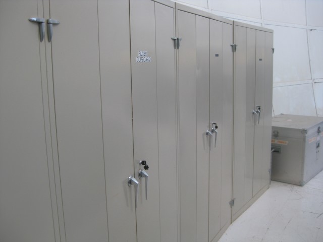
and stored in one of the transparent plastic cases
in the observing-floor optics cupboard.
Only appropriately-trained ING staff should change filters in ACAM.
Sections below:
1 - Mounting a filter in a standard 76-mm holder
2 - Mounting a standard holder in a wheel
3 - Mounting a dispersing element
4 - Removing a wheel
5 - Mounting a non-standard filter wheel
6 - Mounting a filter or custom mask in the focal-plane slide
Appendix 1 - Filters, adaptors, tools etc.
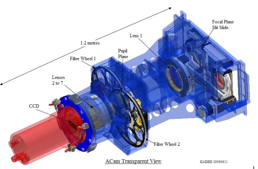
Filters may be inserted in ACAM in one of two near-pupil-plane
wheels
or in the focal-plane slit-slide.
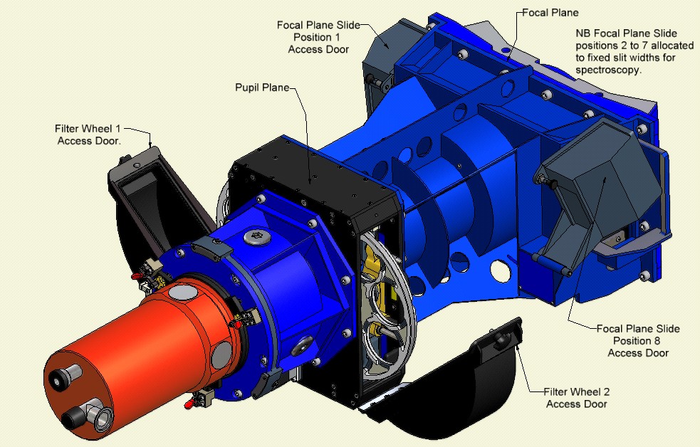
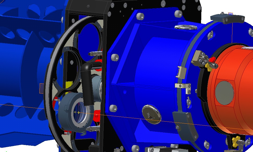
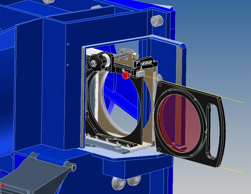
The positions of the wheels and slide are shown in the transparent and
opaque views of ACAM below (direction of light is from right
to left):
See the
ACAM imaging page
for a discussion of the pros and cons of
different locations for mounting the filters.
Most observers will want filters mounted in
wheels 1 or 2.
50-mm filters should be mounted in filter wheel
2 (closest to the CCD) to minimise vignetting.
Light from the full 8.3-arcmin field of view fills a beam
51 mm in diameter at wheel 1, and 42 mm in diameter at wheel 2.
Vignetting of this beam will reduce the throughput across the whole
field of view, not just at the edges.
Filters with very narrow bandpasses (e.g. 15 A) may need
mounting in the focal-plane slit slide, otherwise the change of
transmitted wavelength, as a function of radius in the field,
will effectively vignette targets subtending an angular diameter
of more than a few arcmin.
After making any changes to the contents of the ACAM filter wheels
or focal-plane slide, record the new status in the filter
database. Tip for restricting the filters listed by the database
to only those currently
in ACAM: click on any ACAM entry in the right-hand column (location)
in the displayed table, and the table will refresh, omitting any filters
not currently in ACAM.
Available filter mounts/adaptors
An
inventory of mounts, adaptors, masks, blanks etc
is given at the end of this
page.
Filters of the following sizes can be mounted in the wheels (or in the focal-plane slide):
50/51-mm square and 50-mm, 63-mm and 76-mm circular.
The VPH grism has its own dedicated mount.
In the focal plane, we can also mount 106-mm diameter
circular filters (the Andover set).
Filters in the focal plane can be tilted. The tilters for wheels
1 and 2 should allow tiltsup to 10 deg (limit set by space available),
but have still not been commissioned, due to a problem
with repeatability of the tilt.
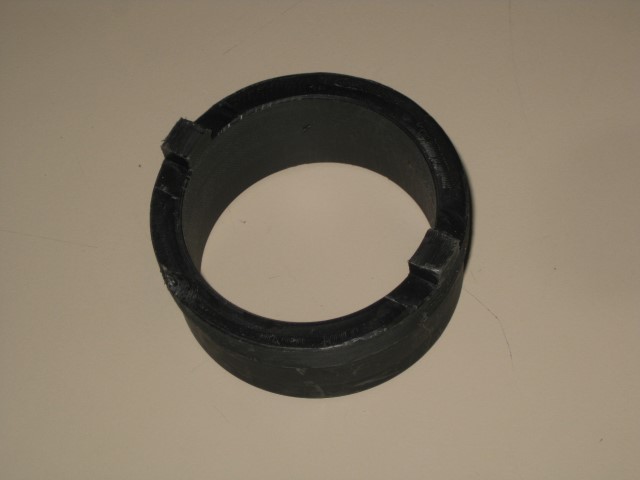
Wheels 1 and 2 accept ING filters up to 76 mm in diameter, mounted
in standard metal holders.
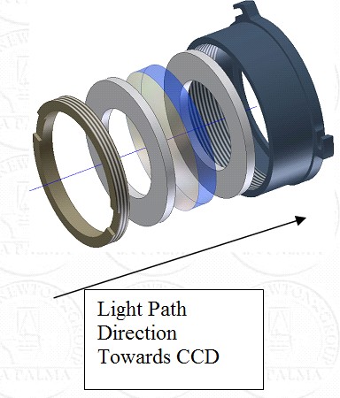
Each filter is mounted in the holder between two grey plastic rings,
and retained firmly in the holder with a screw-thread locking ring
(at left in the image below):
For filters smaller than 76-mm in diameter, one of these
plastic rings will
be an adaptor with a square or circular cutout designed to
support a filter of the given size.
To change a filter in a standard holder:
Light-leaks around narrow-band filters
After installing filters, especially the 50-mm square narrow-band ones,
in the mounts (for wheels 1 and 2),
hold them up to a bright light to make sure that significant amounts
of light are not leaking through at the edges of the CCD-facing
side of the filter.
Typically this appears as a thin bright streak of light, 1 - 2 cm
long, along the junction between the filter and the filter mount.
It's presumably caused by light scattering around the side of the
filter, or inside the filter and escaping at the edge.
Each of these leaks images on the CCD as an arc with radius of
curvature ~ diameter of field of view.
E.g. this image:
shows 3 arcs, one from each of 3 sides of a 50-mm narrow-band filter.
In this case, the arcs are ~ 5 - 10% brighter than adjacent
areas of the image.
They were eliminated by masking off the outer 1 - 2 mm
of the filter.
A few ready-cut black-paper masks for use with these filters are
kept in the exchangeable-optics cupboard.
ACAM has 2 near-pupil-plane wheels for filters and dispersers.
There are 7 positions in each of the standard wheels.
Position 7 should always be kept clear (empty) and position 6
in filter wheel 2 is reserved for the VPH
disperser.
The other positions should all be occupied by filters, to minimise
the risk of problems with wheel imbalance, and with scattered light.
The standard holders will mount in the wheel only one way round.
If a holder containing a filter is swapped between the
wheels, the same side of the filter will face the sky.
To change a standard filter holder in a wheel:
- Point the telescope to zenith, lock it off.
- Take from the exchangeable-optics cupboard case the Allen key.
- Make a note of the filter changes required
before carrying them out.
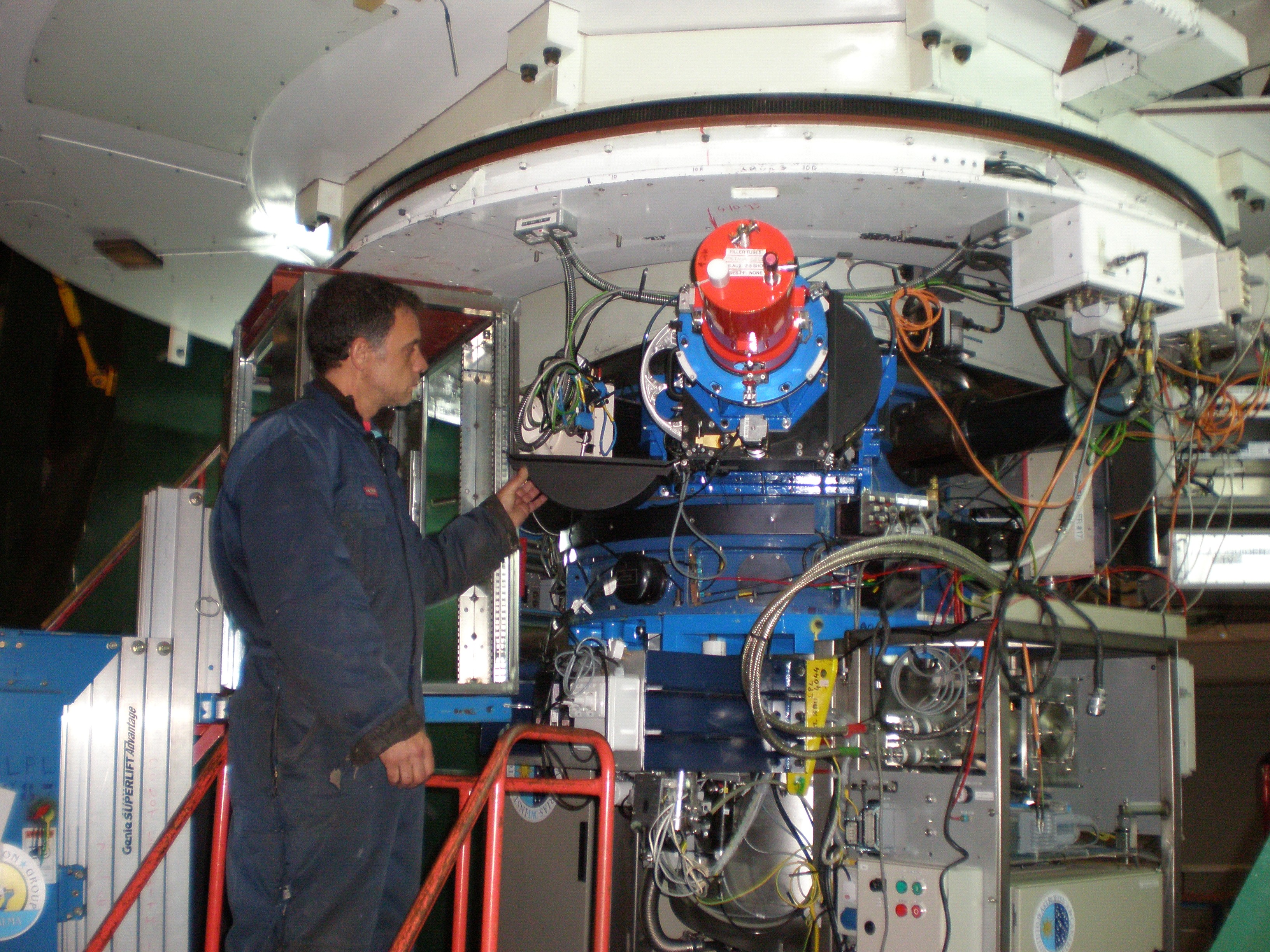
- Position the medium-height (red) step-ladder on the
observing floor just to the left of ACAM for access to filter wheel 1 (as below), or to
the right for filter wheel 2:
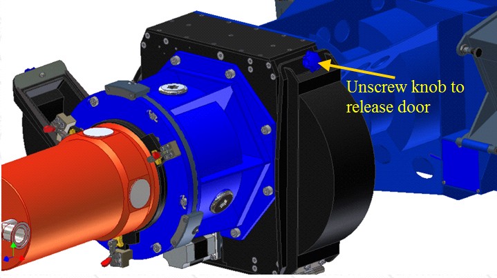
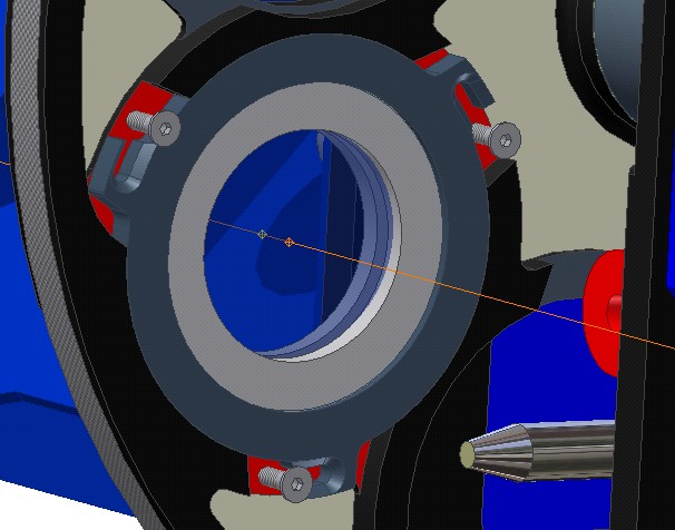
- Unlock the filter wheel access door by
turning anti-clockwise the black knob indicated
(in blue, for clarity) on the image below.
- Support the door so that it does not suddenly drop open
or swing into
something.
Once the filter wheel door is open screw the knob back into
place so it does not get lost.
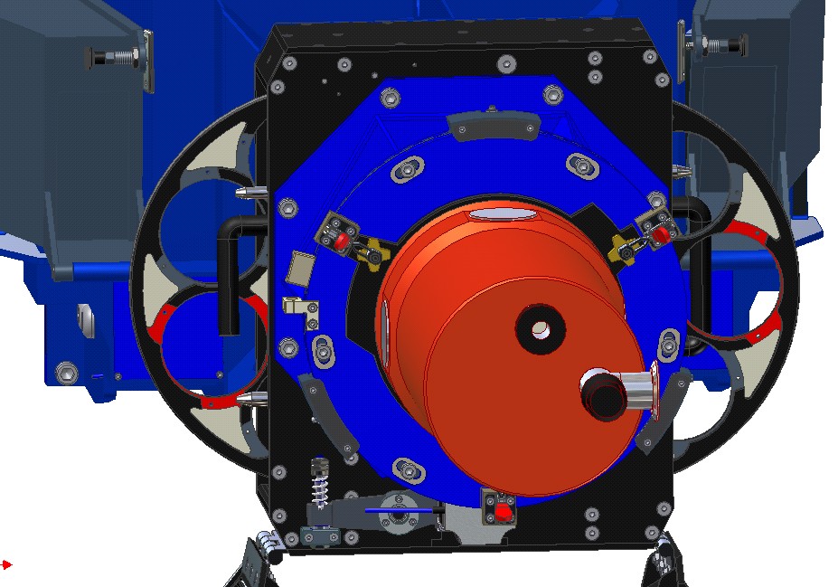
- Rotate the wheel manually so that the filter holder you wish to change
is at the 8 o-clock position for filter wheel 1 as you look towards
the Cassegrain A&G box, or at the 3 o'clock position for filter wheel 2, as
shown below (highlighted in red for clarity).
- Make a note of the
filter wheel position number marked on the
filter wheel.
- To insert or remove a filter holder loosen the 3 screws with the Allen
key (do not remove the screws).
Once the screws have been loosened, keep
a grip on the holder at all times.
- To remove a holder, rotate it anti-clockwise relative to the
mount and the bolts, to this position:
- Then pull the holder
towards you (more exactly, parallel to the optical axis,
in the direction of the cryostat):
- To fix a holder in place, rotate it clockwise until each screw is
in the cutaway slot.
- Tighten the 3 screws with the Allen key (even if there is no
holder present, to prevent them falling out). Do not over-tighten!
- Manually rotate
the wheel (at least 360 deg) to check that there are no obstructions.
- Make sure all tools and screws have been collected.
- Make sure all
filter-wheel access doors are closed and secure.
- Remove all steps
well away from telescope.
- Initialise all 3 mechanisms and move to a few
positions to check operation.
- Unlock the telescope (if you are qualified to do so).
- Update the filter
database to reflect the changes you have made.
- Store the empty filter boxes, and tools, on the appropriately-labelled
shelves of the observing-floor optics
cupboard.
- After the science run, the filter should be removed, if this is
necessary to make sure that the full Sloan set (ugriz) is present in the
wheels.
The daytime duty support astronomer can be asked to do this.
A full list of ACAM-compatible filters can be obtained from the ING filter database.
Dispersers can be mounted only in wheel 2 (they are too thick for
wheel 1).
The current VPH disperser is mounted at position 6 in filter wheel
2, and should not be removed.
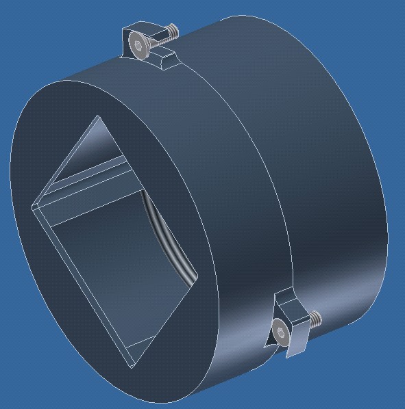
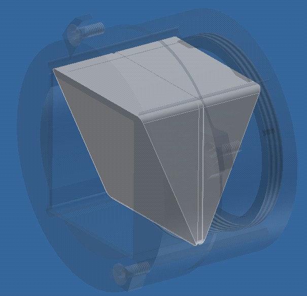
The mount is similar to that used for a standard filter holder but
larger, to accommodate the dispersing element (see images below).
Fitting or removal is from the CCD
side of the wheel 2, as it is for the filters.
The rotational alignment of the disperser relative to the slit
and CCD is critical.
The space envelope allowed for the disperser is a cube, 50 mm on a side.
Once the dispersing element is fitted into its holder, it should not
normally be disturbed.
The holder should
only be removed (or adjusted) by the optics specialist
or instrument specialist.
A unique holder needs to be manufactured for each dispersing element.
Sometimes, e.g. when several filters are to be changed, it's better
to take out the entire wheel, and carry it to the control room
to change the filters there (but beware of control-room humidity
condensing on the cold optics).
To remove a filter wheel:
- Locate a large Allen key (? mm).
- Position the red step ladder on the left (filter wheel 1) or
right (filter wheel 2) of ACAM.
- Release the filter-wheel access hatch by turning the black knob
(at the top) anticlockwise. Support the door so that it doesn't drop,
or swing into anything.
- Screw the knob back into place, so that it doesn't get lost.
- The wheel is held in place by a long bolt passing through
its centre. The head of the bolt is on the far side of the
box (if you're standing on the step ladder).
Use the Allen key to loosen the bolt.
- With your other hand, hold the handle of the filter wheel
and press inwards (against the spring), parallel to its horizontal
diameter, to reduce friction on the bolt.
- The bolt will then turn easily, and can be pulled out.
- Pull the filter wheel out. It weighs ~ 2 kg. If the loading
(by the filter-holders) is asymmetrical, it's likely to spin under
gravity as it leaves the housing. Mind your fingers!
- To replace the filter wheel, carry out the above steps
in reverse.
Standard wheel 1 can be replaced with a special
wheel (cut, but not yet commissioned) that can accommodate up to
four 125-mm filters:
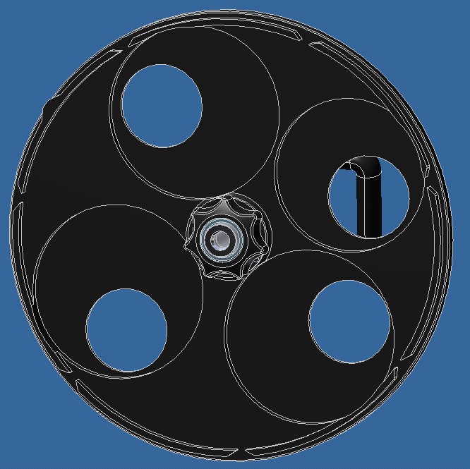
Filters installed in such a non-standard wheels cannot be tilted.
If you think you might need to use such a wheel, contact the instrument specialist
well in advance.
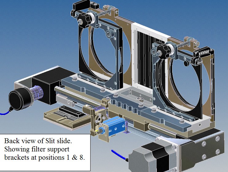
The focal-plane slide (at the entrance of the instrument)
comprises 2 clear apertures
flanking the ACAM slit mask (6 slits of widths
0.5, 0.75, 1.0, 1.5, 2.0 and 10.0 arcsec):
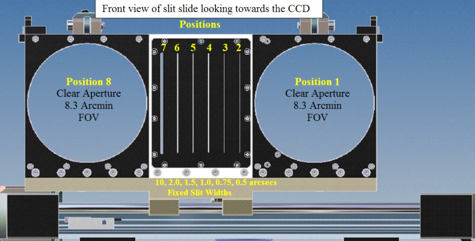
The slide can be moved to 8 positions. In positions 2 - 7, one
of the slits in the mask is placed on axis.
In positions 1 and 8, one of the large circular
apertures is placed on axis. These are usually clear, but can also
accommodate customised slit masks (e.g. the 27-arcsec slit or 40 arcsec
slit) or filters up to 106 mm in diameter (field of view 7.2 arcmin).
The illustration below shows the slide as viewed from the CCD side
(i.e. the side on which the support astronomer will be standing
when changing filters), looking towards the focal plane.
The left pair of apertures (one framed brown in this graphic, one black) is in the
light path when position 1 is requested at the user interface.
The right pair is in the light path when position 8 is requested.
The
nearer frames (black in this graphic) accommodate
filter mounts, while
customised masks can be slotted into the farther frames (brown).
Filters and masks mounted in the focal-plane slit slide should be
removed after the observing run, because
at least one aperture needs to be clear to allow imaging through
filters in wheels 1 and 2.
Mounting a filter (other than 106-mm) in the standard focal-plane filter holder
- Clear some space on a clean working surface.
- Follow the cleanliness/handling precautions advised under Section 1 above.
- Locate the filter.
- Locate the adaptor plate labelled
'for insertion into tilting part of focal plane slide':
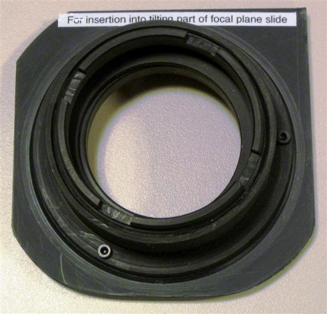
Any of the standard plastic adaptors can be used in the
standard-size mount attached to this plate.
- Mount the filter in the holder.
- Hold the mounted filter up to the light, make sure there are no
light leaks between filter and holder.
Mounting a 106-mm filter in a 106-mm filter holder
- Clear some space on a clean working surface.
- Follow the cleanliness/handling precautions advised under Section 1 above.
- Locate the filter. The 106-mm *ANDV (Andover) narrow-band
filters belonging to John Beckman are stored in wooden boxes
in the GHAFAS cupboard on the WHT's Nasmyth-level walkway (and may be used
only by permission of John Beckman and his team).
- Locate a 106-mm focal-plane filter holder (at least 2 are available):
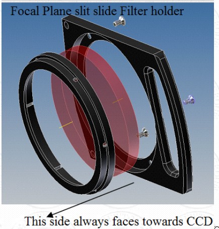 Mount the filter in the holder, and fix it in place with the
retaining ring (three small screws), which always faces the CCD,
regardless of whether the filter is being mounted in position 1 or 8:
Mount the filter in the holder, and fix it in place with the
retaining ring (three small screws), which always faces the CCD,
regardless of whether the filter is being mounted in position 1 or 8:
- Hold the mounted filter up to the light, make sure there are no
light leaks between filter and holder.
Mounting (or dismounting) a filter holder or slit mask in the slit slide.
- Point the telescope to zenith, lock it off.
- Position the red
step-ladder on the observing floor just to the left of ACAM for access
to the slit-slide access door at position 1, or to the right for access to
the door at position 8.
When ISIS is mounted, its protruding control rack means that you'll need
to stand on a wooden block on top of the ladder in order to reach position 8. When you return down the ladder, remember that you are first stepping off a wodden block!
-
By convention, a
filter is usually mounted in position 1, and a mask is usually mounted
at position 8, although in principle it shouldn't matter.
- Before opening an access door use the observing-system
command
acamslit -p 8
or
acamslit -p 1
to send the slit slide to position 8 to make a change at position 1 or
send it to position 1 to make a change at position 8.
This places the
slit slide closest to the access door you will use to make the
change.
*** NB when mounting a 106-mm filter holder in position 1 of the
slit slide, it's better to move to position 7 (rather than 8)
to allow enough space between the end of the
slit slide and one of the Cassegrain electronics racks:
acamslit -p 7
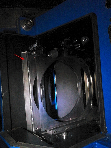
The image below shows position 8 access door being opened.
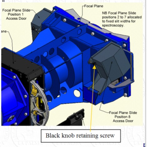
- To open the access door to position 1 or 8, unscrew and remove the
black knob and put it somewhere safe (e.g. in your pocket, not on
a telescope surface). The door lifts up and towards you and needs a firm
initial pull to move it from its closed position.
- Support the access door as you rotate it towards you.
- Once the access door is open screw the black knob back into place
so it does not get lost.
- If installing a filter, first ensure that the locking bolt
shown below (in red, for clarity) is slackened off (anti-clockwise)
to allow the slide
to enter.
- If installing a 106-mm filter, slide the filter holder into the filter
support bracket as shown above, push until aligned with the support structure
and secure
in place with the locking bolt (do not over-tighten).
- If installing a smaller filter mounted in the adapator, slide the
adaptor into the same slot as above, oriented such that the square
(i.e. not rounded) corner
of the adaptor lies under the locking bolt. If installing in position 1,
this means that the white label on the adaptor will be vertical, and
on the left. As above, push home and secure in place with the locking bolt.
- If installing a mask, slide into the slot
shown on the (second) graphic at the beginning of this section.
The 27-arcsec slit mask is a friction fit. It's quite tight
so a firm grip is required when inserting or removing it.
If you know in advance that this change will be needed, try to arrange
for daytime help from Neil O'Mahony.
The 40-arcsec slit mask is not a tight fit,
and requires careful application of tape to cover
gaps on all 4 sides, to prevent light leaks.
- The locking bolt should also be tightened, by hand, when a
holder is removed, so that it cannot work loose.
Blocking any light leaks around the filter holder
- Configure ACAM for imaging through the filter in question.
Take an exposure of the illuminated dome through the installed filter.
- Identify any light leaks on the image.
The table below indicates, for each of 4 positions of a light leak on the
CCD image (as conventionally displayed) the physical position of the light
leak relative to the focal-plane slide (as viewed when standing on the ladder
at ACAM, with the WHT pointing at the zenith).
| Position on CCD | Position on slide
|
|---|
| Top | Right
|
| Right | Top
|
| Bottom | Left
|
| Left | Bottom
|
There is often a significant light leak at the outer edges of the focal-plane
slide, i.e. physically to the left of the slide
when using position 1, and to the right when using position 8, and these
areas usually remain masked off with tape.
- Apply black tape to cover the leak. Ensure that the black tape is
adhering well (old tape may not) to minimise the risk of it falling into
ACAM, and don't let it touch the surface of the filter or vignette the
filter aperture.
The photo below shows such masking
applied along the whole of the left edge of position 1 on the slide:
- Take another exposure to check that the leak has been reduced to an
acceptable level and that blocking the light leaks hasn't vignetted the field.
In this example:
we see that the top part of the field of view is vignetted, i.e.
the masking covers the right part of the circular aperture in the focal-plane
slide.
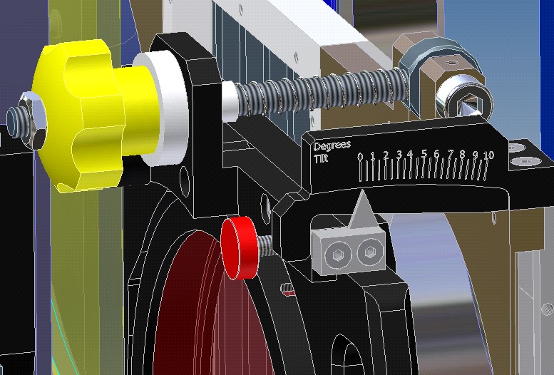
Tilting the filters
- Focal-plane filters can be tilted to fine-tune the central wavelength
of the filter, by manually rotating the central screw highlighted in
yellow in the image below.
- The allowed range is 0 to 10 deg with a resolution of 0.5 deg.
Finishing off
- When you've finished removing or fitting filters,
close the access door and bolt the door in place.
- Make sure all tools and screws have been collected - don't leave any on
top of the Cassegrain control racks!
- Make sure all filter-wheel access doors are closed and secure.
- Remove all steps well away from telescope.
- Initialise all mechanisms and move to a few positions to check operation.
- Unlock the telescope.
- Update the filter database to reflect any changes you have made, i.e.
which filters/masks have been taken out and which have been installed.
NB the 27-arcsec slit mask is
component #2727 and the 40-arcsec slit mask is #4040.
-
If the instrument is in an unusual
state (e.g. filters mounted in both focal-plane slots, or masking
tape needs removing),
warn the support astronomers scheduled for relevant upcoming runs.
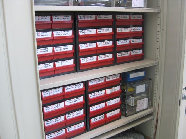
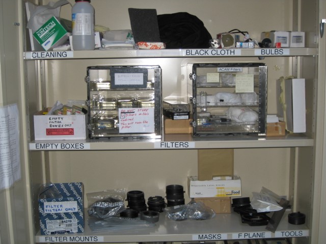
Commonly-used filters, cleaning materials and black card/cloth, together with
the ACAM filter mounts, adpators, spacers, masks and tools
can be found on the top three shelves of the observing-floor exchangeable-optics cupboard:
Less-frequently-used filters can be found in the Nasmyth-level filters
cupboard and the adjacent prime-focus cupboard:
On the 22nd November 2010, after removal of all filters and mounts from ACAM,
an inventory was made of the available mounts, adaptors etc.:
Filter mounts for the wheels
----------------------------
10 black-painted metal mounts for circular filters with
diameter 76 mm,
and 9 metal screw-thread retaining rings.
There is an additional metal ring which doesn't fit the mounts.
These mounts fit in either wheel.  Each mount has 3 projections
which are gripped by the retaining bolts in the wheel.

4 anodised metal mounts of similar size,
and 4 plastic screw-thread retaining rings.
These look like the above, but the surface is more matt.
These mounts fit in wheel 2 but not wheel 1!


Plastic adaptors and spacers for the above
------------------------------------------
These are all circular, diameter ~ 76 mm, and fit inside the
above mounts.

9 thick grey rings, internal diameter 48 mm.

4 similar rings, but with shallow recess, diameter 50 mm, to
support 50-mm diameter circular filters.

16 thin black rings (thin), internal diameter 59 mm,
plus one similar ring, inner diameter 48 mm.

~ 15? adaptors with 48-mm square aperture, with a shallow recess
to support nominally 50-mm square filters - about half of these
adaptors (light grey) take 50-mm square filters, and half (
dark grey) are large enough to take filters with diameter 52 mm.

7 similar adaptors, recessed to support 50-mm square filters,
but with a circular clear aperture, rather than square.

3 O-rings, diameter 76 mm, and 4 with diameter 50 mm.


Blanks for the above
--------------------
6 blanks, diameter 76 mm.


Adaptors for the focal-plane slide
----------------------------------
3 adaptors for the circular Andover filters, diameter 106-mm.


Masks
-----
Box of hand-cut masks for 50-mm circular and square filters,
made of thin black card.


Tools
-----
Allen key for bolts which hold filter mounts in wheel.

Black card.

Bag of spare bolts.
NB as of December 2015, adaptors for 63-mm circular filters are
also available.
Document history: original version July 2009
by Kevin Dee of Engineering & Project Solutions Ltd.