ISIS Overview
ISIS is a dual-arm spectrograph with both arms sharing a common slit unit and dekker slides, as well as optics for imaging- and spectro-polarimetry. Each arm is a conventional
spectrograph, with interchangeable reflection gratings, and a "horizontal" optical layout. The optical components of the two arms, and the anti-reflection coatings
on those components, are optimised
for specific wavelength ranges. The upper arm, the Blue Arm, is optimised for the range 3000-6000Å, whilst the lower arm, the Red Arm, is optimised for the
range 5000-10000Å.
ISIS is mounted below the Cassegrain A&G unit and therefore each arm can view the sky through the A&G unit's Main ND and Colour Filter slides. For example, when ISIS is used
in polarimetry mode calibration polarisers and the quarter- and half-wave retarder plates are mounted in the A&G Main Colour Filter tray.
ISIS doesn't have an atmospheric-dispersion corrector, and so observations should be made with the slit oriented vertically to minimise slit losses from differential refraction.
Although differential chromatic refraction is smaller near zenith, the rate of change of parallactic angle is higher, and these two effects combine to make the relative movement of blue and red wavelengths across the slit only weakly dependent on air mass as a target is tracked. The slit doesn't actively track parallactic angle so the slit orientation should be adjusted every ~1.5-2 hours to minimise the impact of differential refraction.
The A&G unit also houses a calibration unit which provides a tungsten
continuum lamp as a flat-field source, as well as CuAr and CuNe wavelength-calibration arc lamps. Light from the lamps is fed directly into an integrating sphere, the exit pupil of which is fitted with an obscuring disc to
simulate the telescope's entrance aperture obscuration by the secondary mirror structure. The
reverse side of the acquisition mirror is used to feed the calibration light to either arm of ISIS on demand.
- Overall layout
- Polarisation optics
- The slit area
- The image slicer
- Folds and dichroics
- Below-slit filters
- The collimators
- The gratings
- The cameras
- Throughput
- Flexure
- Scattered light
- Wood's anomalies
Overall layout
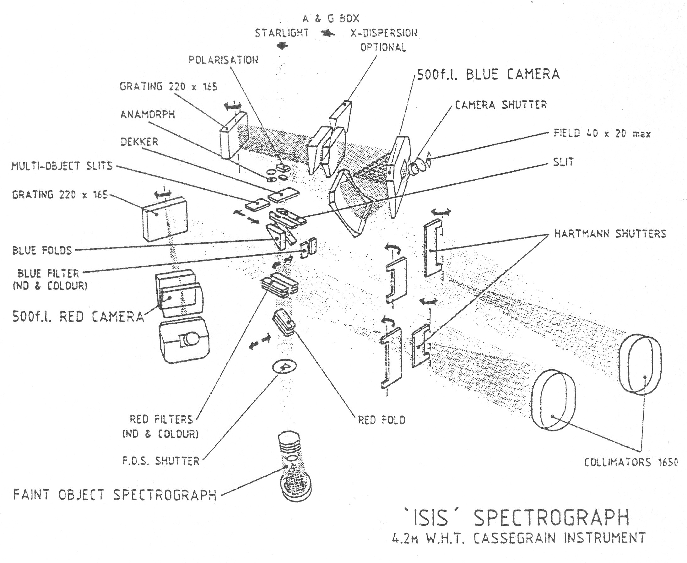
Light is fed into the two arms of ISIS by 45-degree fold mirrors on the optical axis of the telescope at the levels of the respective collimators. The blue-fold mirror can be replaced by a choice of dichroic filters which reflect blue light and transmit red light, allowing simultaneous use of the blue and red arms. This is the most frequently used observing mode of ISIS. The overall layout of ISIS is shown in the following diagram (the Multi-Object mode and Faint Object Spectrograph depicted in the figure have been decommissioned).
Polarisation optics
ISIS is permanently equipped with polarisation optics which can be deployed rapidly using the instrument control system. Polarisers and half-wave
and quarter-wave retarders are located above the slit in the A&G unit, and a calcite slab (Savart plate) is located immediately below it.
The quarter-wave plate is effective over the wavelength range 3000-11000Å and can be set to any position angle, or rotated continuously at a speed of several Hz. The
quarter-wave plate converts circular into linear polarisation, so that the Savart plate (linear beam-splitting polariser) can detect its presence. Rotating the quarter-wave
plate rotates the linear polarisation striking the Savart plate. The quarter-wave plate should only be used for point sources.
A half-wave plate, of 40mm diameter to facilitate long-slit observations, can similarly be set to any angle or rotated continuously; rotating the half-wave plate through n degrees
results in a rotation of 2n degrees of the polarisation vector of the light beam. The half-wave plate is usually mounted below the quarter-wave plate, which gives it the
largest field of view and best slit viewing for linear polarisation studies. It is possible however to interchange these plates, although this requires that ISIS be taken off the telescope.
The Savart plate is located in a tray immediately below the slit, the FCP (Field lens, Calcite, Polaroid) tray. It is effective over the wavelength range 3300-11000Å, and gives two beams separated
by an amount which depends on wavelength, but is in the range 2.1-2.6 mm over the effective wavelength range. The two beams are 100% polarised, orthogonally, and their
relative intensity depends on the polarisation vector of the incoming beam. Comb-type dekker masks are used to avoid overlap between the two sets of spectra produced
by the Savart plate analyser. Use of the Savart plate requires the spectrograph to be refocussed by +9600µm in the blue arm,
and by +9300µm in the red arm.
A polaroid filter is located in the same tray as the Savart plate, and is used when full spatial polarisation coverage is required. It is therefore impossible to use the dekkers
which are used with the Savart plate. However for accurate spectropolarimetry the Savart plate is preferred.
The slit area
The entrance slit is common to the two arms of ISIS. The slit length is 53 mm (4 arcmin), and its width is continuously variable between 30µm (0.14 arcsec)
and 5mm (22.6 arcsec). The slit width is driven by a linear motor, and movement is encoded with temperature compensation.
The slit is polished and aluminised, and is inclined to the optical axis of the telescope at an angle of 7.5 degrees to allow viewing of the reflected image by the A&G box TV camera.
The slit unit itself is a two position carriage, one position contains the conventional long slit, and the other position is a two position cross slide, which in the past
was used for mounting multi-slit masks and the slit end of the ISIS fibre system (both options decommissioned), and which now houses the recently-commissioned ISIS image slicer. This cross slide is also remotely driven by the ISIS PLC controller.
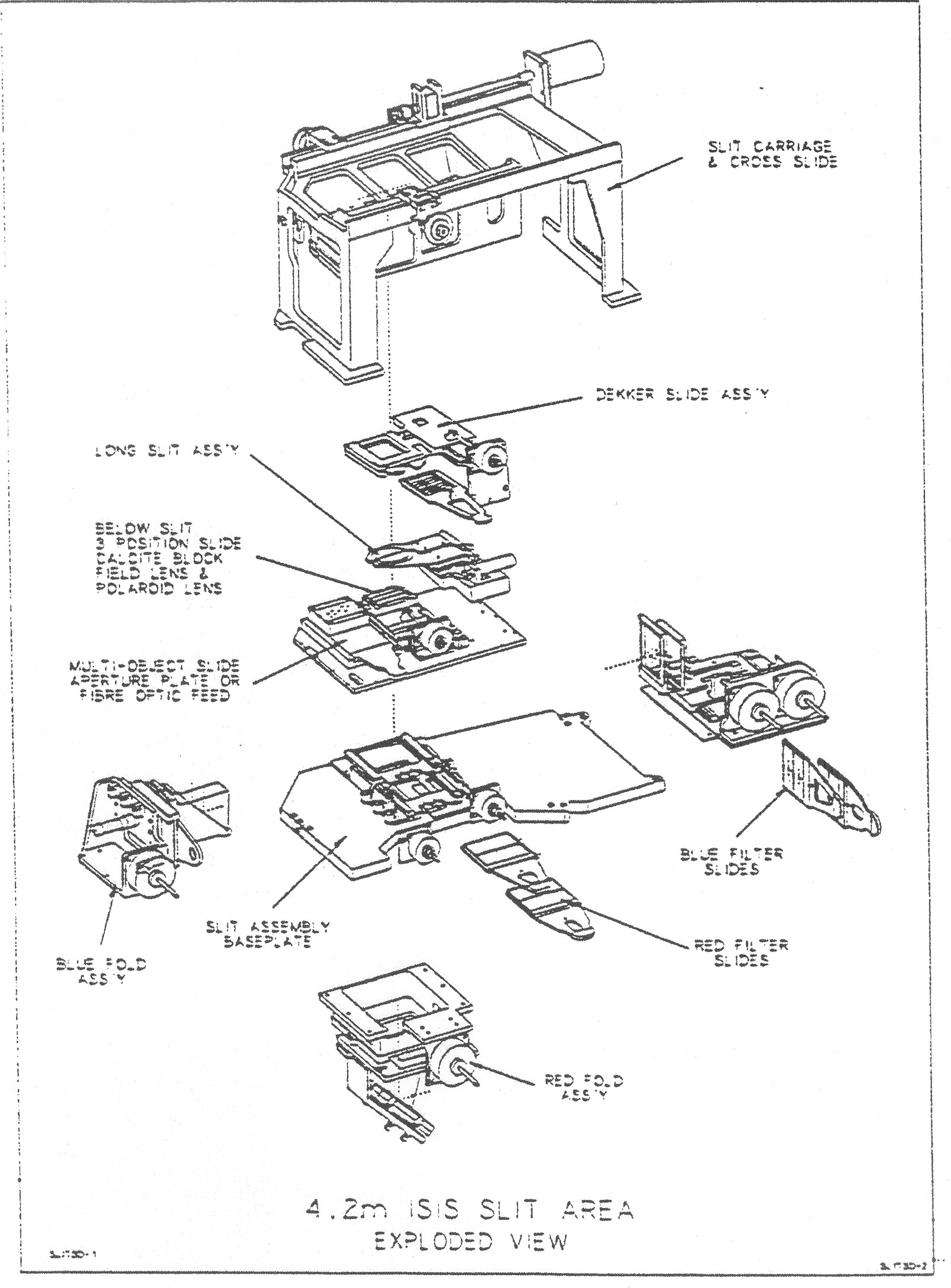
Dekkers masks are mounted in 8-position slides, which are inserted in a driven mechanism located immediately above the slit. The slides are interchangeable in the drive mechanism. Two dekker masks are used when observing, one for general use in long-slit mode (called Observing) to reduce stray light entering the spectrograph and susequent ghosting, and one for spectro-polarimetry use (called Polarisation) used to define the apertures.
The long-slit unit has gaps at each end, and so it is important to use the long slit dekker (in position 8) when observing in this mode, and not to observe with the dekker out (position 1), especially in moonlit conditions. Ghosting is reduced considerably when the long-slit dekker is deployed.
The image slicer
The ISIS Bowen image slicer is pemanently mounted in the slit unit cross slide, and can be rapidly deployed by the control system. It is designed to reduce light-loss at the spectrograph entrance slit by rearranging the stellar image into a series of strips positioned end-to-end along the slit, thus allowing for higher spectral resolution with reduced slit losses. When the image slicer is positioned the
conventional long-slit is automatically moved out of the beam. The image slicer comprises two 2.26-arcsec circular acquisition apertures (slicers A and B) with a 0.45-arcsec mini slit. Slicer A has a broad-band, aluminium coated surface to cover the spectral range
from 310 nm to the near infrared, whereas slicer B has a wide-band dielectric multi-layer
coating to enhance throughput within the region of 390 to 850 nm. In 1-arcsec seeing slicer B is a factor ~1.9-3.3 more efficient than the long slit with width set to project to two pixels (0.42-0.69 arcsec depending on grating).
Folds and dichroics
The blue fold options are controlled by a remotely driven three-position slide mechanism. One of these positions is clear (to observe in the red arm only), and the others can contain a folding prism (now decommissioned)
or a 45 degree mirror (to observe in the blue arm only), or one of a number of
dichroic filters (to observe with both arms simultaneously). There are five interchangeable slides for this slide mechanism, containing the 5300Å, 5400Å, 5700Å, 6100Å and 7500Å dichroic filters and mirrors. The standard dichroic filter is the 5300Å dichroic, but the others are available on request.
If a dichroic filter is in the beam the optical thickness of the material introduces a focus offset for the red arm (the value of the red collimator position is always higher if a dichroic is in the beam).
The 7500Å dichroic provides only a 2 arcminute unvignetted field along the slit, and so is generally used for stellar observations.
The red fold consists of a remotely driven two position slide; one position is clear while the other contains a silver mirror with a reflective stack overcoat to send light into the red arm.
Below-slit filters
There are four 2-position, remotely driven below-slit filter slides, two in
the blue arm beam just after the blue fold, and two below the blue fold but
above the red fold, used for the red arm. There is a range of neutral density
and colour filters for use in these slides. The blue arm filter slides were
normally used to hold neutral density filters for when the IPCS (now
decommissioned) was in use; the red arm filter slides are used to hold
blocking filters to cut out second order blue light. Care must be taken when
mounting the slides since, although the red arm slides do fit in the blue arm
slots and vice-versa, cross mounting them will cause vignetting.
The collimators
Both ISIS collimators are off-axis parabaloids with a focal length of 1650mm, and
provide a collimated beam of 150mm diameter. The coating material on
each collimators is optimised for the wavelength range of the corresponding camera,
and is silver with a reflective stack overcoat for the red collimator, and
aluminium for the blue camera.
As with most astronomical grating spectrographs, an image of the pupil is formed
on the grating in order to minimise the grating size required.
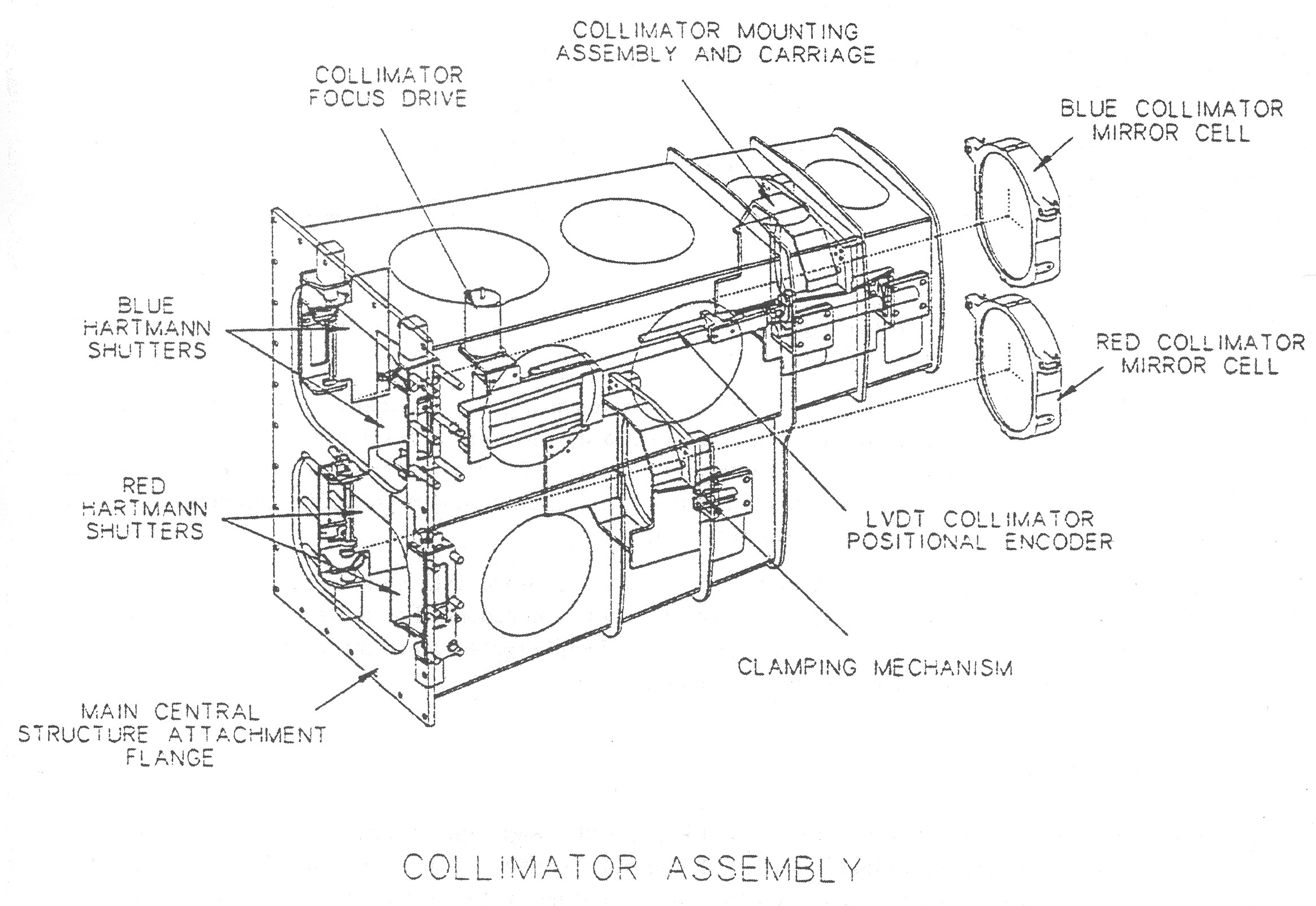
The collimators are remotely driven by stepper motors, and their position is
encoded. The spectrograph focus in each arm is normally fine-tuned by driving the
collimators; the collimator position is repeatable to better than 10µm. With
no extra refractive components (dichroics, prisms, Savart plate, filters) between
the slit and the collimators, the nominal focus positions for the collimators are
5100µm for the blue arm, and 9300µm for the red arm. The spectrograph
should be focussed with the collimators within ±3000µm of these nominal
values, otherwise the spectrograph will be astigmatic, that is, the best focus on
a spectral line will result in a degradation of the spatial resolution along the slit.
If the optimum spectral focus set by moving the collimator would move the collimator beyond this nominal range, then instead the spectrograph should be re-focused approximately by moving the detector using the capstans, and then fine-focused using the collimator so that the collimator remains within the anastigmatic range.
The gratings
Nine gratings are available for ISIS, five for the blue arm, and four for the red arm. The names of the gratings indicate (i) the method of manufacture, (ii) the number of lines per millimetre, and (iii) the arm of ISIS in which they are deployed. Therefore grating R1200R is a ruled grating with 1200 lines/mm and is used in the red arm, whereas grating H2400B is a holographic grating with 2400 lines/mm, and is used in the blue arm. Eight of the nine gratings are copies of ruled masters manufactured by Milton Roy, and the H2400B holographic
grating was manufactured by Jobin Yvon. All gratings have a lined area of 154 x 206 mm. Grating R1200B was ruled in two halves; this
can be seen quite easily when the grating is held up to the light.
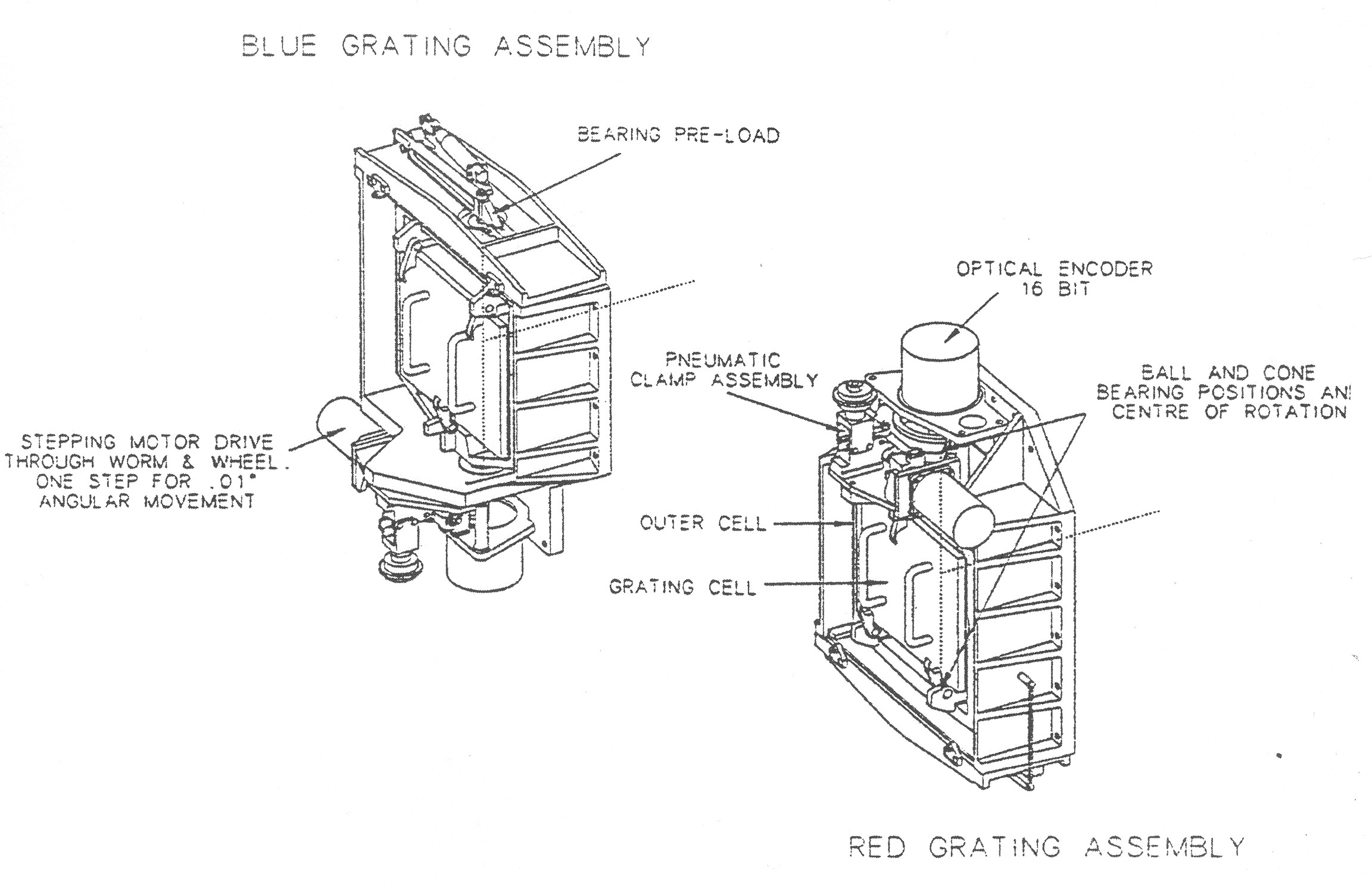
The grating cells in each arm are identical, and so all gratings can be positioned in the grating assembly of either arm (see figure).
Gratings can be mounted either blaze-to-collimator (i.e., grating normal tilted to camera) or blaze-to-camera (i.e, grating normal tilted to collimator). Deployed blaze-to-camera gives a somewhat lower dispersion, and as the anamorphic reduction factor is
reversed this configuration has a greatly reduced slit-to-plate reduction factor, especially at high dispersions. The ISIS gratings are almost invariably used blaze-to-collimator,
and the slit widths given in the tables for the blue and red arms are for this configuration.
The efficiencies of the ISIS gratings as a function of wavelength have been measured in the laboratory and are shown in the figure.
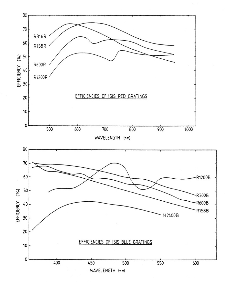
Note that the holographic grating has a lower efficiency than the ruled gratings, and
is also used at a grating angle such that the beam overfills the grating, resulting in some additional light loss.
A single silver-coated plane mirror is also available in a grating cell. This was originally
intended for alignment purposes, but it can be used in place of the gratings for
direct imaging with a plate scale of 14.9 arcsec/mm. To use the mirror for imaging it should be mounted in the grating cells, which should then be set to the autocollimation angles (30800 millidegrees for the
blue arm and 35500 millidegrees for the red arm).
The grating-cell angles, which define central wavelength, are driven by a stepper motor from the ISIS PLC controller, and their positions are encoded by optical absolute encoders. The units for these
mechanisms are millidegrees, and the encoders are accurate to 3 millidegrees, and repeatable to 2 millidegrees. The grating angle offsets are grating independent.
The cameras
The ISIS blue and red cameras are of a folded Schmidt design, with a focal length of 500 mm giving a scale of 14.9 arcsec/mm along the slit. The air-glass surfaces of the refracting elements of the two cameras are coated with anti-reflection coatings optimised for the respective wavelength ranges, and the reflecting elements are coated with silver plus a reflective stack for the red arm, and aluminium for the blue arm. The default CCDs are the thinned, AR-coated
EEV12 in the blue arm, and the deep-depletion, fringe-suppressed and AR-coated
Red+ in the red arm. Electron-multiplying, low-light-level CCDs
QUCAM2 and QUCAM3 are also available for each arm.
Throughput
Nearly all of the light losses within ISIS are due to reflective and air-glass surfaces. There is a small loss of light (<10%) in each camera due to optical vignetting; and for the highest dispersions there is some additional loss due to the beam overfilling of the grating.
The historical throughput of ISIS is discussed in detail in
ING La Palma Technical Note no. 88. Briefly, the throughput of the red arm with no grating was measured to be 51%, and that of the blue arm with no grating to be 42%. These measurements were made with a HeNe laser at 6300Å, and thus for the blue arm are slightly beyond the wavelength range over which it is optimised. The values for the red arm are also slightly low as the red fold mirror in use at the time was below its specification.
The end-to-end sensitivity of the WHT+ISIS with the current default detectors
and the R300B and R158R gratings over the wavelength range 3200Å-9300Å is shown here. The peak
apparent AB magnitude corresponding to a star observed at the zenith giving one
detected photon/second/Å is ~18.6 at ~4000Å and ~18.2 at ~6500Å.
Flexure
In the original specifications for ISIS flexure was to be limited to no more that 5µm/hour along and perpendicular to the slit during telescope tracking. The figures show daytime measurements with a narrow dekker and arc lamps of the flexure (i.e. flexure between the dekker and CCD) in 13.5µm pixels at different elevations (90, 75, 60, 45, 30 and 15 degrees) over a range of position angles of the instrument rotator (-90, -45, 0, 45, 90, 135, 180, 225 and -90 degrees).
Flexure is greater in the blue arm than in the red arm, and the original specification is generally exceeded in both arms. Also, there appears to be hysteresis in the flexure. It's strongly recommended therefore that observers requiring accurate radial velocities should take arc lamp calibrations at each pointing, and frequent arcs, e.g. every hour, if monitoring a target, to limit the impact of instrument flexure on results.
Scattered light
Scattered light in ISIS is minimised by the use of optimised anti-reflection coatings, and if scattered light would be a serious problem for a particular observation it's
important to exclude light of wavelengths, other than those required, from the optics by using appropriate blocking filters, particularly wavelengths outside the range for which the coatings are optimised.
Diffuse scattered light has been shown to be below 2% by observations during commissioning of quasar absorption lines known to be completely black.
Ghost images are caused by stray reflections within the spectrograph, and can either be in-focus images or images of the pupil. Pupil images take the form of the telescope pupil
with the central obstruction, even if the illumination is from the comparison lamp system, because the illumination from the integrating sphere is designed to mimic exactly
that of the telescope.
There are a number of known ghosts in ISIS. Briefly,
- A ghost spectrum parallel to the primary spectrum, which is seen in blue arm observations when a dichroic filter is used. It is caused by light reflected off the back
surface instead of the front surface of the dichroic. It is strongest at wavelengths in the crossover region. The offset on the detector from the primary spectrum
is defined by the thickness of the dichroic, and is typically a few tens of pixels.
- A Narcissus ghost pupil image which is caused by reflection between the surface of the CCD or its surrounds and the cryostat window. This appears strongest
when caused by strong spectral features just off of the CCD, for example when looking at a Copper-Argon source at blue wavelengths at low dispersion, when the
ghost is caused by reflection of the strong red lines from the surrounds of the CCD. If it is due to a continuum source the pupil image will be smeared in wavelength,
and may be difficult to recognise as such. The intensity of this ghost is at the level of 10-4 of the intensity of the primary source.
- A grating ghost caused by reflection between the grating and the aspheric plate of the camera when using the R158R grating in the red camera. The ghost images of all wavelengths add, so this ghost can appear quite strong.
- An in-focus ghost caused by a reflection from the folding prism in the red arm.
- Rowland ghosts, which are caused by periodic errors in the ruling of the gratings, appear around strong emission or comparison lines as satellite lines at a level of >10-5 of the parent line's intensity.
Wood's anomalies
Wood's anomalies are discussed in detail in
ING La Palma Technical Note no. 76
in the context of INT IDS gratings. For a reflection grating which produces a range of diffracted light in successive orders diffracted away from
the normal then in some order, at some critical wavelength, the diffracted light lies in the plane of the grating; it is not possible for light beyond this point to be
diffracted behind the glass of the grating. The power which would be sent into the "forbidden region" is therefore redistributed back into the allowed orders. This
power appears as an addition to the spectral response, with a sharp cut-on at the critical wavelength and a steep decline to the red, and the additional efficiency is
almost entirely polarised perpendicular to the grating rulings. This additional power is in no sense a reflection or a ghost image; it is a genuine enhancement of
efficiency of the grating because the light from two orders has been combined.
Wood's anomalies occur at wavelengths λ = d(sin(α)±1)/m,
where d is the grating groove separation, α is the grating angle (the angle between the grating normal and the collimator axis), and m is a positive or negative integer.
There are known Wood's anomalies in ISIS at 7200Å (1200 grating, m=2), 6400Å (600 grating, m=4) and 4400Å (600 grating, m=-2).


