 | |||
|

| Home > Astronomy > ISIS > Miscellaneous information |

|


Miscellaneous information
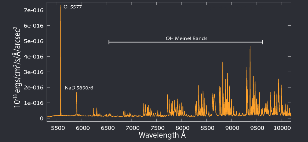
Airglow emission lines in the red armA detailed critique of all contributions to the La Palma Night-Sky Brightness is given
here.
FITS headers with telescope parkedOn some occasions it's necessary to know the sky position angle of the slit in calibration images taken with the telescope parked at zenith, for example, in spectropolarimetric twilight flat fields. The calculation of the sky position angle from raw FITS header entries is described below.
The Cassegrain mount position angle, m, slit sky position angle, θ, ISIS slit offset, θ0,
and parallactic angle, q, are related by When the telescope tracks a target during normal ISIS observing, the mount moves to maintain a fixed slit sky position angle, θ, and the values of mount position angle, m, and parallactic angle, q, at the start and end of each exposure are written in FITS header keywords MNTPASTA, MNTPAEND and PARANSTA, PARANEND repectively.
When the telescope is parked at zenith, it's parked just outside the formal zenith blind spot at
a zenith distance zp=0.28o, as listed in FITS header keywords ZDSTART, ZDEND, and
in azimuth ap=298.64o, as listed in keywords AZSTART, AZEND. The parked mount position
angle is usually, but not always, mp=45o, as listed in keywords MNTPASTA, MNTPAEND.
The telescope's declination therefore must satisfy (φ-0.28o) ≤ δ ≤ (φ+0.28o), and so the ratio cos(φ) / cos(δ) must be in the range ~0.997 to ~1.003. Therefore from (3),
with the telescope parked 0.28o from zenith, its azimuth must be within ~4.4o of the
parallactic angle over all values of azimuth, and so The slit sky position angle can be calculated from (2) when the telescope is parked in an arbitrary position, e.g., at zenith distance 45o to take dome flat field images, but of course telescope azimuth is no longer a suitable proxy for parallactic angle, and the latter must be calculated explicitly. Scattered light and ghost imagesISIS does, however, exhibit a number of generally low-level ghost images, caused by stray reflections within the spectrograph. The main ghost images which can manifest themselves, listed more-or-less in order of relative significance, are:
Known scratches on the gratingsR158R: clean, only few very tiny stains R158B: one scratch 10 cm long, one scratch 5 cm long, both in central area, two finger prints at edge, few small stains R316R: two parallel scratches 0.3 cm long, one scratch 0.5 cm long, one small stain R300B: one scratch 1.5 cm long, one scratch 2 cm long, one scratch 1 cm long, all close to one of the edges, two parallel scratches 3 cm long in the central area, few small stains R600R: few small stains R600B: few small stains R1200R: four scratches 0.3-2 cm long close to shorter edge of grating, one scratch 0.5 cm long on the opposite shorter edge, about 14 scratches 0.1-1 cm long close to longer edge of grating R1200B: three scratches 0.5-3 cm long close to shorter edge of grating, four scratches 0.2-1 cm long close to longer edge of grating, four shallow scratches 6 cm long close to central area, one small gray stain H2400B: one small stain, area very slightly dimmer covering around 40 % of the grating surface Dichroic focus offsets and ripple profilesDichroic Corrective Coll. Movement (µ) ---------------------------------------- 5300 +860 5400 +1270 5700 +1350 6100 +1340 7500 +1320Although light to the blue arm reflects off the front surface of the dichroic (bfold 2) and mirror (bfold 1) the two optics are not necessarily coplanar in the dichroic slide. For example with the D5300 dichroic, switching from mirror (blue arm only) to dichroic (both arms) requires a positive adjustment of the blue collimator by a ~+100-500µ, dependent on grating used. This switch is rare in practice, but it's important to check for such focus offsets in the blue arm when using any of the dichroics. Observers should note that the dichroics introduce 'ripples' into the blue arm light with a specific wavelength profile. These can be removed by careful flat-fielding techniques when reducing the data, but observers may wish to avoid the problem altogether. Each dichroic has a characteristic reflection profile, following plots will effect your dichroic choice (plots for each dichroic linked from here). Available colour filters
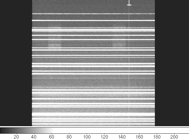
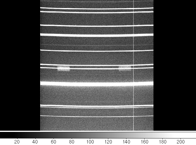
and their focus offsetsThe following values have been measured for the red arm filters: Filter Focus shift (pix) Corrective Coll. Movement ------------------------------------------------------------- GG495 0.58 +800 RG630 0.54 +750 GG395 OG550 NG4 BG28 BG39 OG515Values for the blue arm filters will appear here: Filter Focus shift (pix) Corrective Coll. Movement ------------------------------------------------------------- NG4 BG28 GG495 0.92 1038 RG630 1.26 1413 BG39 Og550If an observer is in doubt about which filters to use, if any, they should ask advice from their support astronomer. SA's should note that the filter slides can only be mounted in the appropriate locations, i.e. RfiltB slides can only go in the red arm in position B, RfiltA slides can only go in red arm position A. The filter slides are all labelled correctly (as of 22/2/99), and their contents are given below aswell as written on the slides themselves. The diagram below shows the filter slides schematically, in each case the filter written uppermost is in Position 1. The positions 1 and 2 are the same for each filter and the corresponding ICL commands (rfilta, rfiltb bfilta and bfiltb for positions 1 and 2) correspond to these positions. ___________ | _______ | B filt A B filt A1 B filt B | |___1___| | GG 495 NG 4 BG 39 | _______ | RG 630 BG 28 OG 550 | |___2___| | | | R filt B R filt B1 R filt B2 R filt A \ / RG 630 BG 39 NG 4 OG 550 \ / GG 495 OG 515 BG 28 GG 395 \ / | | | | _____ Image rotation caused by the dichroicsDichroic Image rotation in pixels top to bottom ----------------------------------------------------- 5400 1.00 5700 2.86 6100 1.33 7500 1.20Arc lines were aligned along the detector columns with the mirrors, so that the "Image rotation" was effectively zero. The dichroics were then put in and the values for "Image rotation" in the table above refers to the offset between the arc lines at the top of the CCD and at the bottom. These values are in EEV12 pixels (i.e. 13.5 microns), the slit extent was 400 pixels, and the 1200B was used. In all cases no image rotation was found between the mirrors in different slides, only the dichroics with respect to the mirrors. For the 5300 dichroic used with the R600B grating and EEV12 detector image rotation is 0.8 pixel over a slit extent of 966 pixels. Slit view and CCD orientation
                                             East
                                            /|\
                                             |
                                             |
                                             |
For PA=0:                                    |
                                              ------------> North


For PA=90:                                   ------------> East
                                             |
                                             |
                                             |
                                             |
                                             |
                                            \|/
                                             North
The slit is ALWAYS viewed lying left-right on the acquisition camera no matter what the PA of the rotator is i.e. the acquisition camera is permanently fixed with respect to the slit. ISIS red arm astigmatism problemDuring the 2002-01-03 night, the spatial focus was determined using different ISIS dicroics. The spectral focus was fixed in the afternoon for the Red and Blue arms of ISIS without any dichroic. During the night, we corrected the spectral focus offset introduced in the Red arm for every dichroic placed in the beam. The general set-up of the instrument was: ISIS Arm Grating Central wavelength Collimator Position -------------------------------------------------------------------------- Red R316R 7500 8784 Blue R600B 4500 6279 The results obtained observing a bright star close to zenith and using a slit width of 1 arcsec are summarized in the following table. ISIS arm | BFOLD position | Best telescope focus ________________________________________________________ Red Clear 97.75 Blue Mirror 97.75 Red 6100 97.70 Blue 6100 97.75 Red 5700 97.70 Blue 5700 97.70 Red 4500 97.75 Blue 4500 97.75 ________________________________________________________ ISIS focus offset caused by gratingsISIS focus offsets caused by gratings were re-measured in 2012 using the dichroic 5300. The RED+ CCD was used on the red arm and EEV12 CCD on the blue arm of ISIS. The test was performed on 7th June 2012 and repeated on 28th October 2012. In the first occasion, the focus was fixed using R316R (red arm) and R300B (blue arm) gratings, on the latter occasion, the focus was fixed using R1200R (red arm) and R1200B (blue arm) gratings. The focus offsets from the measurements on 7th June 2012 were recalculated to correspond to fixed focus using R1200R (red arm) and R1200B (blue arm) gratings. The final results are averages of the two values, with an uncertainty corresponding to a standard deviation. The results are useful, for example, for support astronomers when using different gratings during one service night. Optimally, a support astronomer should take into account focus offsets of all the gratings planned to be used in one service night, and finish the afternoon set-up with a collimator value suitable for all of them. For example, if in one service night the gratings to be used on the red arm are R1200R and R158R, with the default D5300 dichroic and order-sorting filter GG495: the optimal collimator value for R1200R grating alone is 10960μ (see here) but now that also R158R grating is in use, the optimal collimator value for both is 1163/2=582μ less than 10900μ as the grating R158R will introduce a positive offset of 1163μ.
ISIS Focus               R158R/B   R316R/R300B     R600R/B    R1200R/B     H2400B
-----------------------------------------------------------------------------------
Red Arm (Dichroic in)  1163 ± 149   801 ± 175     502 ± 258     0 ± 0
Red Arm (Dichroic out)  157 ± 202  -113 ± 225    -330 ± 283  -691 ± 42
Blue Arm (Dichroic in)  184 ± 113   412 ± 28       10 ± 4       0 ± 0   -1095 ± 110
Blue Arm (Mirror)       -48 ± 45    306 ± 199    -564 ± 8    -515 ± 26  -1435 ± 184
The plot below shows how spectral resolution degrades as a function of
collimator offset from the optimal collimator focus, 8837μ in this example
(not mm as wrongly indicated in the gif image). These measurements
were performed using Tek4 CCD instead of currently used RED+ CCD.
|
| Top | Back |
|
