ISIS Setup
Overview
Roughly one month before the observations take place you should have
read the observer's proposal which you can access on the schedules page from within the ING network by
selecting the programme reference. The
proposal should contain all the details of the required configuration
(CCDs, dichroic, gratings, blocking filters and central
wavelengths). You should ask the PI to confirm the setup in your pre-run contact email.
You should be able to advise on
the use of a blocking filter (more details
here).
You should also check that the required configuration is met by the engineering
schedules. If this is not the case contact the WHT manager.
Starting the observing system
A detailed procedure describing how to start and shut down the observing system can be found
here.
Physical setup: dichroic, dekker and gratings
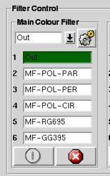
Note 1: When LIRIS is mounted the ISIS polarisation filters
(MF-POL-PAR and MF-POL-PER), located in the main colour filter slide in the A&G box, are
replaced by the LIRIS polarimetry half-wave plates along with the instrument change.
The SA rostered on the first night following a change from LIRIS
back to ISIS should check on the mimic that the ISIS polarisation filters
have been replaced. Be aware that on occasions other instruments
can be scheduled between LIRIS and ISIS runs. If the ISIS polarisation filters
aren't summarised in the mimic send an email to the ISIS specialist.
Note 2: If you're switching
from an ISIS polarisation or image-slicer run back to a long-slit spectroscopy run, remember to move or change
the relevant components before starting the new setup:
When switching from spectro-polarimetry mode you'll need to change to the long-slit Obs dekker, and move the calcite, half- or quarter- waveplates, and probably mainfiltc out of the optical path, and also bring the blue and/or red collimator values to the non-polarimetry anastigmatic range (ISIS Setup for Spectropolarimetry).
When switching from imaging polarimetry you should swap the mirror in the imaging-polarimetry arm to the required grating irrespective of what is indicated in the ISIS MIMIC (Image Polarimetry with ISIS).
After imaging-polarimetry or image-slicer runs switch back to long slit mode by running the longslit command in the pink ICS window, command-line prompt currently SYS>:
longslit
You can now proceed to physically change the dichroic, dekker and gratings as needed (note
that even if these components as needed are indicated on the mimic
you should check that they are actually deployed).
To change the dekker, dichroic or below-slit filters first move the dichroic out of the beam for easy access:
bfold 0
Then move the dekker out:
dekker 1
Then unlock the slit door:
slit_door open
You can now open the slit door located on top of the red cryostat. Inside
you will have access to the dichroic, filters and dekker. Remove the filter slide (RFILTA) to protect filters from being accidentally damaged. Pull the pin
that holds the dichroic and carefully slide the dichroic out. Put the
dichroic back in its sealed box at the bottom of the WHT observing floor cabinet.
Take the new dichroic out of its box and carefully slide it in
and lock its pin holder.
Proceed in a similar way with the dekker unit. Just pull it out, put
the dekker back in its box and introduce the other one in the unit. Ensure
that the dekker is fully seated in the slide.
Close the slit door securely by snapping the locks. Finally lock the slit door
in the control window:
slit_door close
put the dekker in clear position:
dekker 8
and update the mimic:
setdichroic <dichroic name>
setdekkerset <dekker name>
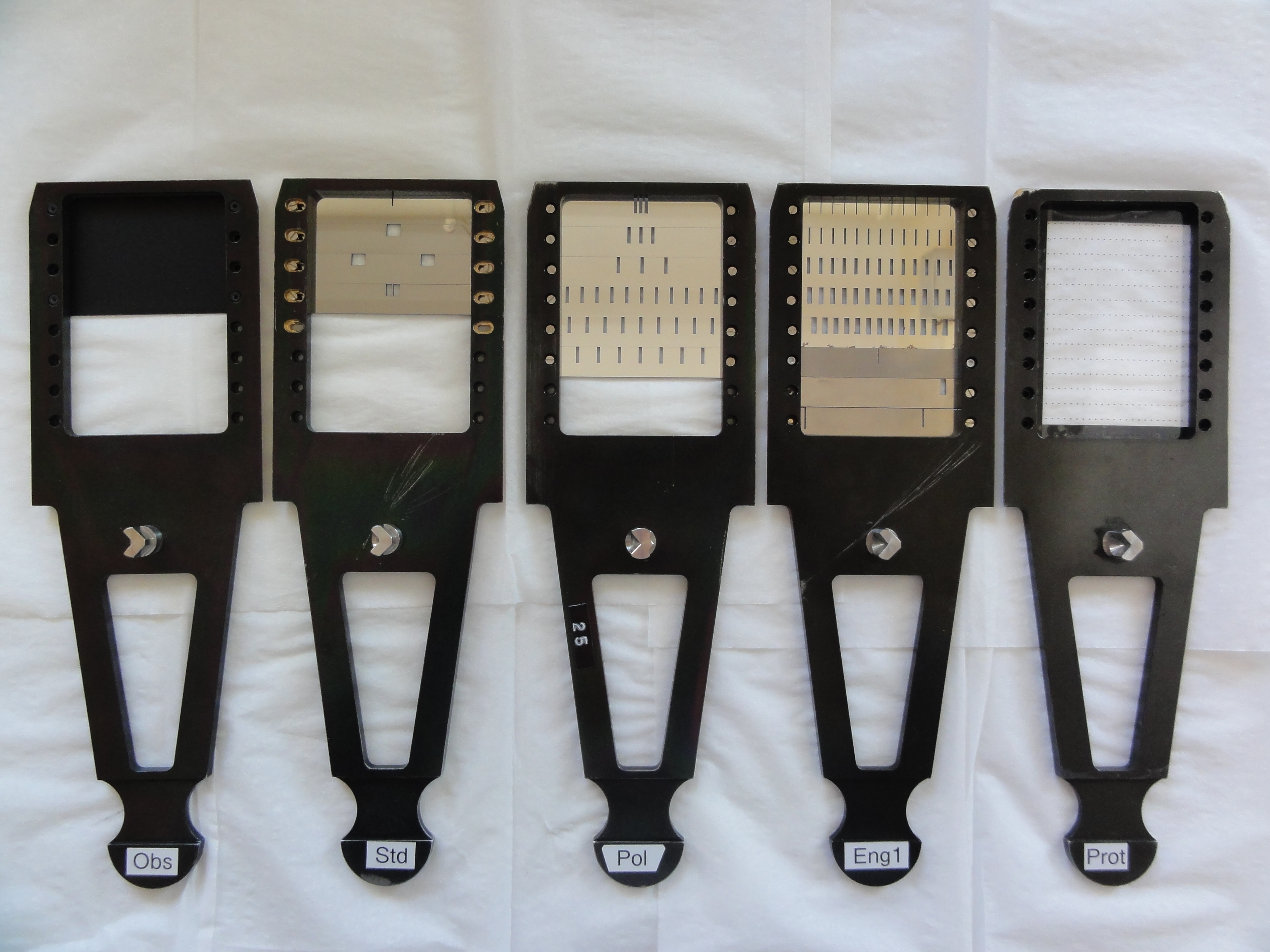
The dekker name can be either observing, standard or polarisation.
Here are images of the available dekkers.
The Prot dekker is used to protect the slit when ISIS is off the telescope.
For the standard ISIS runs the observing dekker should be used. It
has the same clear parts as the dekker standard but also eliminates
ghosts in
the blue arm caused by a dichroic.
If you have changed a dekker click on the "Update filters" button in both the "ISIS Observer" and "ISIS Eng." tabs of the Instrument Control Console so that the dekker drop-down menus are updated.
Now you can proceed to change the gratings, e.g.:
setgrating red R1200R
to change the red grating to R1200R.
Then answer yes to access the grating door. The doors are then unlocked and
can be opened manually. To release a grating hold it by its handles, push the "open" switch and gently pull it out from its holder. Place it back in its box and insert the new one.
You must ensure when you load a grating in
the grating cell that
the blaze arrow on the back of the grating points towards the left
for the red arm, and towards the right for the blue arm, i.e. gratings should be inserted
blaze-to-collimator. If the grating is inserted in the opposite sense, i.e.
blaze-to-camera, then throughput is reduced by up to an order-of-magnitude.
Never touch the surface of a grating. Inspect visually all gratings that you put in and out and compare with a
list of
known scratches on the gratings. Report any unusual findings to the ISIS instrument
specialist.
Once a grating is in place hold it by its handles and push the "close" button (place your fingers away from the three grating clamps!). Finally, securely close the grating doors by snapping the door locks.
Set the
slit width to ~0.5-0.7 arcsec; don't close the slit more than this since
the intrinsic line-width will not be fully sampled on the CCD.
slitarc 0.7
Set the red
and blue central wavelengths to the values requested by
the observers, e.g.:
cenwave red 7500
The red fold mechanism should
always be left in the mirror position ("rfold 0", or "rfold mirror") to direct light to the red arm.
Set the blue fold mechanism to position the dichroic to the required position:
bfold 2
to observe in both red and blue arms simultaneously,
bfold 1
to observe in the blue arm only.
bfold 0
to observe in the red arm only. Note that arc lines falling
in the attenuated wavelength range of the dichroic will appear stronger
in single-arm configurations.
Insert the order sorting filter GG495 if needed:
rfilta 3
Deploy the comparison mirror and turn on calibration lamps:
agcomp
complamps cune+cuar
Set the correct CCD window:
window red 1 "[555:1520,1:4200]"
(should be OK for red arm + REDPLUS)
window blue 1 "[585:1550,1:4200]"
(should be OK for blue arm + EEV12)
Do not bin the CCD.
Use fast readout speed to quicken the process:
rspeed red fast
rspeed blue fast
Cryostat alignment
You are now ready to align the cryostat, that is, align
the spatial axis with the detector rows, ensure that the CCD is
not tilted with respect to the focal plane, focus the
spectrograph, and finally check that the collimator position for the best
spectral focus also produces a good spatial focus. Complementary information on this
procedure is available.
Note that the spectral and spatial directions are not orthogonal in either arm of ISIS. By default the spatial direction is aligned with the detector rows since this simplifies
sky subtraction. It is of course possible to align the dispersion direction with the detector columns instead, but in this case precise alignment won't be maintained on-sky because ISIS does not have an ADC.
In order to check for the rotation, it is good practice
to first check that the CCD spectral focus and CCD tilt are broadly OK. The reason for this
is that lines used by setup script need to be reasonably and uniformly sharp across the CCD.
If you are going to use a dichroic, check the rotation with the dichroic deployed since the dichroics
can introduce some image rotation, especially in the blue arm. Also, if you notice an unexpectedly
large rotation between two gratings it's wise to check the grating is firmly seated before
embarking on rotating the cryostat.
Be aware that configuring
the setup is an iterative process, and that there is "cross-talk"
between e.g. rotating the cryostat and adjusting the cryostat tilt.
Therefore if you need to modify the tilt after
setting the rotation, re-check the rotation again. After the final
mechanical intervention for rotation and tilt, tighten the rotation bolts, Allen-bolt locks and capstan
clamps, and make a final check that rotation and tilt remain acceptable.
Finally, with the spectrograph
anastigmatic (see below) fine-tune the focus by adjusting
the collimator (this process does not involve mechanical intervention
with the cryostat).
CCD rotation
Start IRAF and load the
isis package: in a shell on whticsdisplay type
iraf, and at the
ecl prompt in the iraf window type
ecl> ing
ecl> isis
Start by moving the collimators to their approximate autocollimation values, 5400µ in the blue arm and 9300µ in the red arm, taking into account the focus offsets of the optical components deployed, listed
here.
Next check that the CCD spectral focus and tilt are more or less OK. Take a test exposure:
glance red 3
glance blue 60
Check that you get reasonably intense arc lines; it's important that arc lines aren't saturated, and those used in the setup scripts should have signal-to-noise of at least ∼15 to obtain consistent results when using the calibration scripts.
Now take an arc exposure:
arc red 2 "Rotation test"
In IRAF, run the isis_rotation script with mode 1=arc lamp. Mode 2 is used when aligning the spectral direction with the CCD columns by using a narrow dekker, the 0.3-arcsec dekker in position 2 of the standard dekker slide, illuminated with a continuum lamp.
isis> isis_rotation r2345678
The IRAF script
isis_rotation.cl extracts the spectra of an arc image in two windows separated
spatially and cross-correlates them to determine any pixel shift due to rotation. The shift is then converted into a detector
rotation offset in micrometer units (mm).
The pixel shifts are measured directly on the arc image and are the fundamental numbers; the detector rotation and micrometer offset are calculations from a scale conversion
and may be occasionally wrong (e.g. if the cryostat is rotated with respect to the nominal position).
For a well-aligned cryostat you should aim to have the pixel shifts between top and bottom as reported by the rotation script <0.5 pixel,
preferably <0.25 pixel.
If the rotation is larger than this limit, loosen the cryostat rotation bolts which attach the cryostat mounting
ring to the spectrograph mounting ring, with an Allen key. Never loosen
the two recessed bolts, which fix the spectrograph mounting ring to
the spectrograph. Apply the recommended micrometer offset to the cryostat, clockwise (+) or anti-clockwise
(-) as required. For anti-clockwise
rotation of the cryostat you should lower the value on the micrometer, and for
clockwise rotation you should increase the value on the micrometer. Re-tighten ~3 of these bolts
which are the closest to the three capstans A, B and C.
Iterate this procedure until the rotation is within limit, then re-tighten
all rotation bolts with the Allen key. In order not to
over-tighten them, engage the long end of the Allen key
in each bolt, and rotate the short end until it is reasonably "finger tight". Finally, back-off the
rotation micrometer by a few complete turns, e.g. four, so it is not in contact with the stop even
with flexure, to
ensure pick-up noise is never transmitted through it to the cryostat.
Note that for the R1200R,B gratings and the H2400B grating, arc lines are slightly curved
by approximately 2 pixels from centre-to-edge of the standard window.
CCD tilt
Take two exposures, one with the left Hartmann shutter closed and one
with the right Hartmann shutter closed. Do not move the Hartmann shutter
until the frame has been read out. The order in which the exposures are
taken is not important. Make sure that spectral lines are not
saturated and that the collimator is in the anastigmatic range (see CCD
focus below).
You can use one of the
following scripts:
1-
this script to take the
necessary images in both arms
2-
this script to take the
necessary images with the red arm only
3-
this script to take the
necessary images with the blue arm only
This is basically what the scripts do:
rhart l
(left Hartmann shutter closed)
arc red 4 "test hart l"
rhart r
(right Hartmann shutter closed)
arc red 4 "test hart r"
rhart 0
(both Hartmann shutters open)
Now analyze the data with IRAF. First display one of
the spectra taken and note the
y-coordinates of three well-spaced spectral lines, i.e. near the bottom, centre
and top of the detector. The positions need to be accurate only
to within 10 pixels. They must not be saturated, so check red-arm spectra carefully, and choose lines
that are strong (signal-to-noise at least ∼15; the arm lamps are faint in the blue arm), that are
not doublets or blends, that are not too close to other lines and that are
not located in the vignetted part of the CCD. Run
the isis_tilt task, e.g.
isis> isis_tilt r2345678 r2345679 y1 y2 y3
where y1, y2 and y3 are the y-coordinates of the three fiducial lines, e.g.
600, 2000 and 3400, respectively.
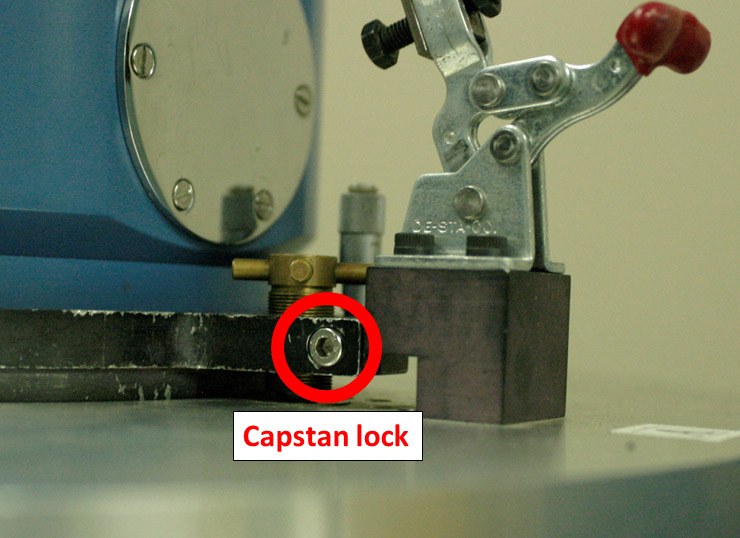
Apply the recommended capstan turns, if any, in order A, B, C.
The capstan micrometers should be backed-off when turning the capstans.
When adjusting the capstans their Allen-bolt locks should first be loosened with an Allen key (3mm, stored in the torque screwdriver's box), and locked again after final adjustment. Never forcibly turn a capstan
which is locked, and don't overtighten the Allen bolt (finger tight with the long arm of the Allen key engaged is good), in both cases to avoid wearing the threads on the capstan and/or faceplate.
To adjust capstan A, loosen its M5 bolt using the torque screwdriver, and loosen slightly the M5 bolts of capstans
B and C to prevent buildup of mechanical tension if applying large adjustments
to capstan A (small adjustments to a capstan can be effected by loosening only its M5 bolt), while supporting the cryostat with your other hand. Then proceed similarly with capstans B and C.
Never completely loosen all three capstan clamps simultaneously; this would cause the cryostat to fall. Ensure the M5 bolts of each capstan are tightened to a torque
of 3Nm using the torque screwdriver after each adjustment cycle, in the order A, B and C; this constrains the most degrees of freedom soonest.
You should aim to have the top-bottom and left-right tilts
restricted to <0.5 pixel, and preferably to <0.25 pixel of Hartmann shift. This means each capstan offset - overall, top-bottom and
left-right tilt for A, B and C - would be less than about 0.1 turn (but the important numbers in judging the alignment are of course the Hartmann shifts). In this way degradation of optimal spectral focus will be negligible.
When you're happy with the capstan settings, back-off their associated
micrometers again if you've used them to measure the capstan positions,
to avoid transmission of pick-up noise to the cryostat. It's good practice at this stage to take another arc to
check that there's been no induced change in rotation
caused by the tilt adjustments.
Proceed similarly for the blue arm.
CCD spectral focus
The nominal autocollimation positions of the collimators with no extra refractive components
(dichroics, filters, polarisation module) between the slit and the
collimators are ~9300μ for the
red arm, and ~5400μ for the blue arm with the D5300 dichroic (i.e., not the fold mirror) positioned. The spectrograph should be focused with the collimators
within approximately ±2500μ of these nominal positions,
taking into account the focus offset of optics in the light path, to restrict
astigmatism due to de-collimation of the beam
incident on the grating to be less than the intrinsic line-spread of the telescope and instrument.
The anastigmatic collimator ranges for combinations of the D5300 dichroic and GG495 blocking filter are listed
here,
and the focus offsets for the remaining dichroics are listed here.
If the optimum spectral focus set by moving the collimator
would move the collimator beyond
this nominal range, then instead the spectrograph should be coarse-focused by moving the cryostat
using the capstans
so that the collimator remains within the anastigmatic range. So, conceptually the focus
procedure involves setting the red and blue collimators
to 9300 and 5400 respectively with no additional optics in the beam,
reducing the Hartmann shifts as reported by the focus script to <1 pixel
by adjusting the respective cryostat capstans, and
then fine-tuning the focus to its optimum value by adjusting the
respective collimator values.
If you subsequently deploy or change e.g., a filter then the appropriate focus
offset must be applied by adjusting the collimator.
Therefore, the focus procedure is:
rcoll 9300
bcoll 5400
Take two exposures, one with the left Hartmann shutter closed and one
with the right Hartmann shutter closed. Use the same procedure as for CCD
tilt above.
Now run the isis_focus task:
isis> isis_focus r2345678 r2345679
If the Hartmann shift reported is >1 pixel turn each cryostat
capstan by the
recommended amount. Alternatively, if the Hartmann shift reported
is <1 pixel
apply the recommended collimator shift, i.e.
rcoll "value"
bcoll "value"
where value=original_value+shift.
Repeat this sequence until the recommended collimator shift is
⪅200μ and the collimator value is in the anastigmatic
range.
Don't forget to note the A, B, C,
& D micrometer values down in the CCD capstan settings folder.
Finally, you can make a "sanity check" of the spectrograph setup by measuring the position and FWHM
of three lines (top, centre and bottom of CCD) in three different positions
(left, centre and right to ensure there's no significant rotation or focus
change across the detector.
You should also check that the final central wavelength setting gives the correct spectral range by comparing arc spectra with an atlas
of CuAr+CuNe lines. This is especially important for the higher resolution gratings, which
have a correspondingly smaller spectral range.
Update the
ISIS setup database when you are finished. The
entries in this database are a useful complement to the nightlogs to identify specific setups when troubleshooting.
Ideally the dichroics would block light at wavelengths below the cross-over from entering
the red arm, making a blocking filter in the red arm unnecessary. In reality, the
dichroic
response is not perfect and some blue light can enter the red arm. ISIS
is sensitive to light from ∼3000Å to ∼10000Å, and so second order blue
light can contaminate red-arm observations at wavelengths redder than ∼6000Å,
especially for targets which have strong blue continuum or line emission.
If second-order contamination would be a problem a GG495 blocking filter,
which blocks wavelengths below ∼4950Å and has ∼95% throughput at the
remaining wavelengths, should be deployed.
If the spectrograph is focused with the GG495 blocking filter in the light
path the
collimator offset is about +800 microns.
Second-order contamination can also affect blue-arm observations when
the D7500 dichroic is used, with the second-order contamination being
caused by wavelengths bluer than ∼3750Å. This can be prevented
by using a BG395 blocking filter,
but when this is used
of course the blue arm is no longer sensitive to first-order light with wavelengths
below ∼3950Å.
In the case of red-arm-only observations at wavelengths beyond ∼6000Å, i.e without a dichroic deployed, the use of a blocking filter is usually
mandatory to avoid second-order contamination. Even if the science targets are
very red the flux and telluric standards may not be.
The observer must ultimately confirm whether a blocking
filter is to be used or not, but ought to be aware of the potential
effects of not doing so.
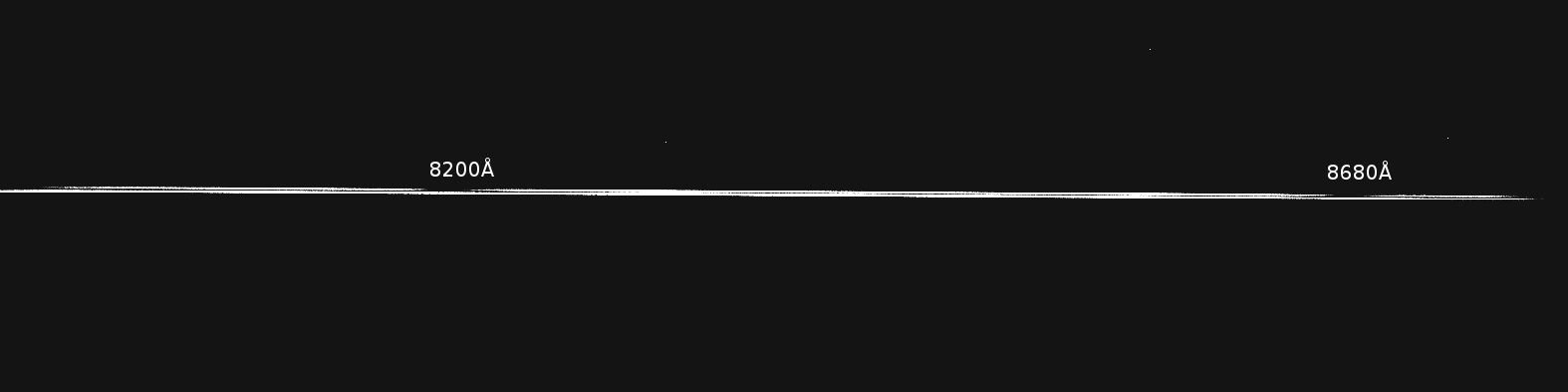
This
z-scaled image shows an integration with the
R1200R grating centred on 8384Å of a bright, A0 star at zenith
distance 52-degrees with no
dichroic or blocking filter deployed, and with the slit oriented
vertically. The fainter "ghost" upper spectrum is the second-order
spectrum of the blue wavelength region centred on 4191Å. It
is displaced spatially from the first-order spectrum due to cross-dispersion by
atmospheric differential refraction along the vertical slit, and the separation of the two orders ranges from ~1.6-arcsec
at the blue end to ~1.3-arcsec at the red end because of the wavelength
dependence of differential refraction. The broad absorption features
at ~8200Å and ~8680Å in the upper spectrum are second order H-delta and H-gamma
respectively.
Re-focusing when changing dichroics or gratings
When the spectrograph is focused
there are fixed offsets for the red collimator in case the dichroic is
changed (see
miscellaneous
information).
When the spectrograph is focused with a different grating, check the
focus offset caused by gratings.
Setup for spectropolarimetry
For spectropolarimetry, set up the spectrograph as described
here.
Here
is the procedure describing a change of ISIS polarimetry filters MF-POL-PAR
and MF-POL-PER to the LIRIS half-wave plates in the Main Colour Filter Tray.
For ISIS spectropolarimetry, you will need to replace the LIRIS
half-wave plates with ISIS polarimetry filters. Follow the same procedure as
above but the other way around.


