 | |||
|

| Home > Astronomy > ISIS > Throughputs of dichroics |

|


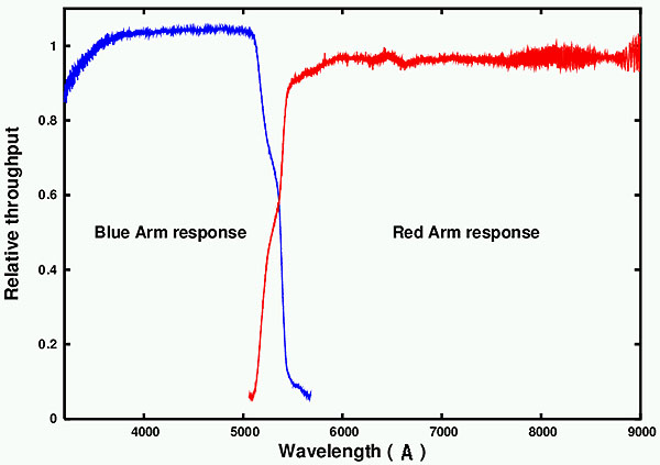
Throughput of the standard 5300 dichroic and blue fold mirrorUnless otherwise requested, the default ISIS dichroic deployed is the D5300. Those interested in using a different dichroic should clearly indicate this and justify its use in the observing time application, and should contact the ISIS instrument specialist if in doubt. The following plots illustrate the response of the dichroics in the blue and red arms. The dichroic is mounted on a movable slide next to a plane mirror (the blue fold mirror). With the mirror deployed in the light path all of the incoming beam is directed to the blue arm. With the movable slide out of the light path all of the incoming beam is directed to the red arm. With the dichroic deployed in the light path blue light is reflected into the blue arm and red light is transmitted to the red arm, so that red- and blue-arm integrations can be made simultaneously.The blue curve in the figure below shows the dichroic response (blue light reflected off the front face of the dichroic) divided by that of the fold mirror (blue light reflected off the fold mirror), i.e., this curve is the throughput of the dichroic relative to the fold mirror. The plane mirror 'normalisation' level is therefore dependent on the mirror's absolute reflectivity. Note that the response of the standard dichroic is better than that of the the fold mirror over a significant part of the wavelength coverage; this is a real effect which observers should bear in mind when doing blue-arm-only observations. Note also that ripples in throughput are very small compared with the other dichroics (below). With the dichroic slide removed from the beam, light passes directly on to the red arm. The red response curve shown below is the dichroic (transmission) response divided by the 'straight-through' response. The curves are quite flat, and the small throughput ripples, which are of the order 1-2%, can be removed by flat fields. However, there is a ~5% efficiency loss in the red arm when observing with the dichroic compared with red-arm-only operation. The exact throughput at the crossover wavelength in the plot at ~5336 Å is not precisely as implied from the Y-axis because the blue and red plots are normalised to different scales as discussed, but it is below ~70%. In summary, the throughput of the default D5300 dichroic is better than that of the other dichroic filters available (exceeding >95% in the red arm). The dichroic reflectance is ~4% better than that of the blue fold mirror in the 3500-5100 Å region. Throughput ripples, in particular in the blue arm, are much less pronounced than for the other dichroics, and the reduced throughput crossover region is narrower.
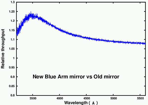
The throughput of the blue mirror is larger than 95% according to the manufacturer. The relative throughput of the standard blue mirror with respect to that installed in the 5400-dichroic unit is shown in the figure below. Note that the throughput is >10% better.
Throughputs of the additional dichroicsThe following plots show the blue and red responses of the rest of available ISIS dichroics. They are labelled according to their half-power point on the blue side (i.e. where response drops down to 50% in the normalised curve).Again, in each figure the blue curve shows the dichroic response divided by the response of the corresponding fold mirror (and so the plane mirror 'normalisation' level is different in each plot) Apart from the significant ripples, three of the dichroics actually show better transmission than their respective fold mirrors over a significant wavelength region. As with the standard 5300-dichroic, this effect is real. These throughput ripples can present a problem for data quality if flat-field normalisation is not carefully carried out. As observations are taken at different telescope positions compared to afternoon flat fields, which are taken at zenith, there is a likely shift of the spectrum on the detector due to flexure, and so it samples different parts of the dichroic ripple. To correct for this shift one should take flat field exposures at the same telescope position as the observations. This is of course quite time consuming, so the default D5300 dichroic is preferred as far as possible. The impact of throughput ripples compounded by instrument flexure is illustrated in the example plotted below, where a normalized flat field is displayed along with the ratio of two normalised flat fields taken at different telescope positions. It is seen clearly that the ratio of these two flat fields is not flat, especially in the bluer part of the plot (left). The images were taken with the 5700 dichroic and the R600B grating set at central wavelength 4720Å. 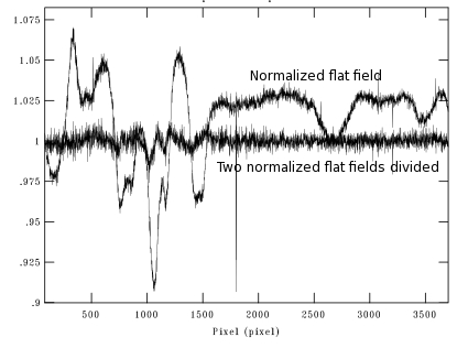
Finally, and as for the D5300 dischroic, the red-arm response curves shown below are the dichroic transmission response divided by the 'straight-through' response. These red-arm curves are quite flat for all dichroics, and the slight ripples, which are of the order of 1-2%, can be easily removed. There is a 10% efficiency loss (compared with 5% for the standard 5300-dichroic) in the red arm when observing with the dichroic, as compared with red-arm-only operation. It should be noted that all dichroics exhibit a far-blue leak. Therefore, observations in the red arm at wavelengths >6000Å of targets with significant blue flux demand the use of an appropriate order sorting filter to ensure that the second-order blue light leak contamination of the first order red end is blocked. |
| Top | Back |
|
