 | |||
|

| Home > Astronomy > IDS > INT-IDS Operation Manual |
INT-IDS Operation Manual
1. Introduction
In this guide, the following syntax will be used:
Back to Top 2. Safety
Back to Top 3. Troubleshooting
Back to Top 4. Areas of the Telescope
The control room is located at the floor of the building, and has the
following key areas:
Back to Top 5. Preliminaries
Back to Top 6. Filling the IDS cryostat
IMPORTANT! The cryostat on IDS should be filled at least every 13 hours. During normal working week days, the ops-team working at ING will fill it at midday, so observers should fill it just before and after the observing night. During weekends and public holidays, the observer at INT is in charge of ensuring that the cryostat is filled at intervals not exceeding the 13 hour limit. If for any reason the observer at INT cannot ensure that the cryostat will be filled within 13 hours, he/she should contact the WHT Operator to coordinate the filling of the cryostat with sufficient notice. Public holidays are marked in green in ING schedule.
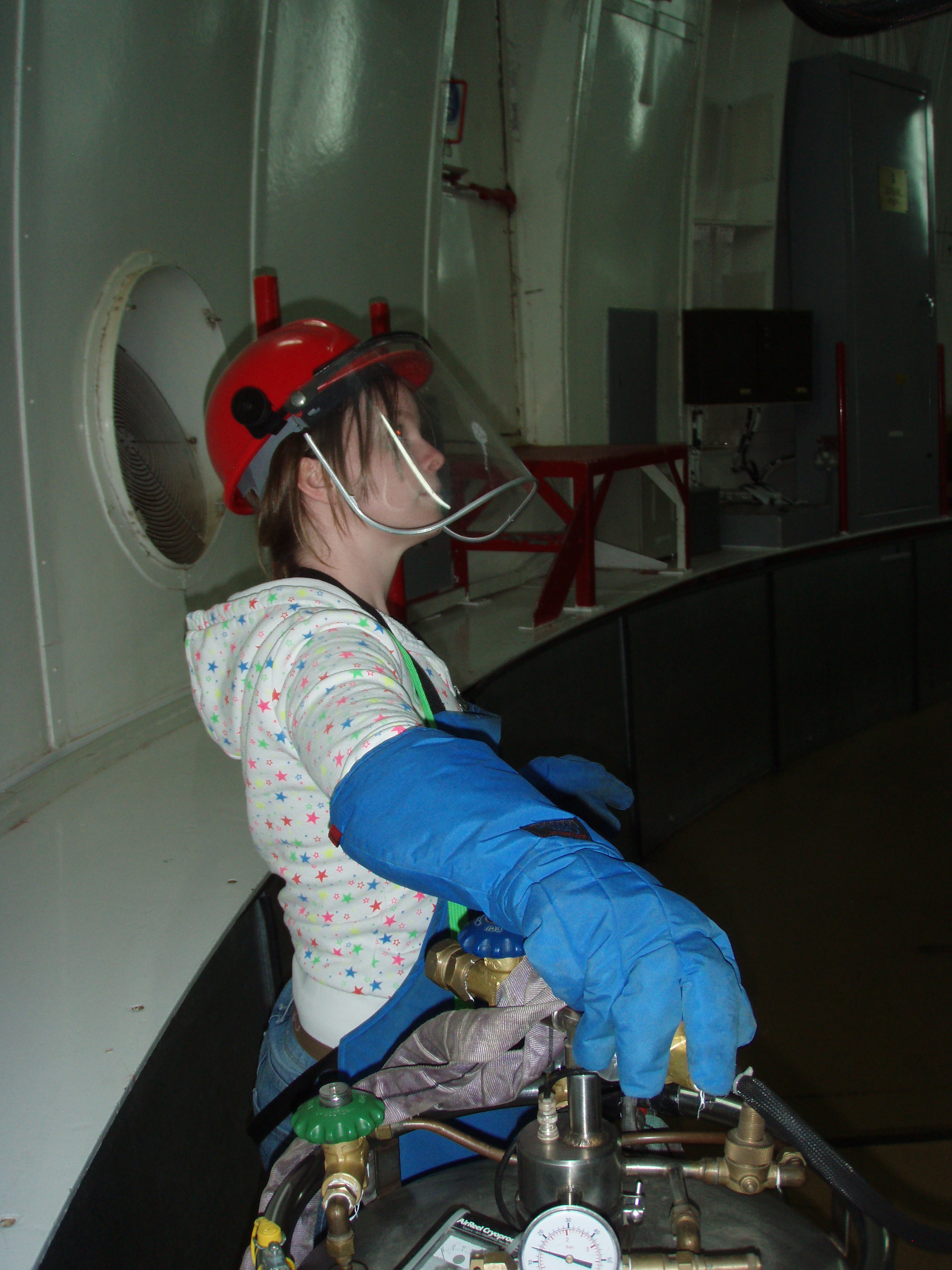
IMPORTANT! Wear the safety helmet (with the visor in front of your face), apron and gloves when filling the cryostat (example). BEFORE filling the cryostat you MUST mindfully read the information in the page Liquid Nitrogen Cryogenic Health and Safety.
Please, follow the safety instructions below for avoiding that anyone accidentally moves the telescope when cryostats are being filled with LN2:
Back to Top 7. Zeroset and Pointing Calibration
Note that a Zeroset ONLY should be performed if the TCS is restarted or if the telescope pointing is bad.
Please call the WHT OSA before restarting the TCS or doing a Zeroset as in many cases redoing the Zeroset can be
avoided.
During the first night of your run the SA will show you how to do it (in case you need to do it later during your run ONLY in the situations described above and after consulting the WHT TO).
Back to Top 8. Switching the TCS between Computer and Engineering Mode
Back to Top 9. Setting up the Acquisition Camera
In the orange DAS6 window on the TCS, define a 3x3 binning of the acquisition
camera, which allows fast readout and display cycles. Type the command:DAS6@miranda> bin 3 3
On the ICS mimic, check that the acquisition camera AG0 is centred on the slit. That is, in IDS mimic it should have numbers close to:TV X: 498000 TV Y: 500000 (if these coordinates are very different please write a Fault Report and if you have problems with the acquisition inform this to the WHT TO).
In ds9, you should check that the image has been inverted in the y-direction (from the top menu choose Zoom then check that the Invert Y option is checked) and that the rotation is set to '0'. A green cross '+' for the instrument rotator centre and a red cross '+' at the slit centre should also be displayed. In case they do not appear, then from the top menu 'Region' --> 'Load Regions...', you can load the most recent region "IDS_centres_bin3" file for 3x3 binning at /home/intobs/Documents/*.reg. To load the regions you need an image being displayed. You can acquire one by pressing Field. If the green and red crosses disappear after starting acquisition, click on ds9 top menu File, Preserve During Load, and check the box Regions. The field of view of the Acquisition camera (AG0) covers an area of approx 75 x 70 arcsec². Back to Top 10. Loading Catalogues
Check which objects are loaded into the TCS current list of targets by typing:
USER> out term
If there are objects loaded which you don't need, then the command
USER> erase
can be used to delete all targets from the current list. Note that the catalogues will still be
stored on the computer, but will no longer be loaded into the TCS. It is possible to load your own catalogue onto the TCS with all your targets in it. They can be created with any text editor, and should be saved as {your_catalogue}.cat. The filename must not contain any upper-case letters. Each line of the file should contain one object and its coordinates in the following format: [object] [ra] [dec] [epoch] [!comments]So, for an example object SN 1987A: sn1987a 05 35 27.9 -69 16 10.00 J2000 ! commentThe line must be delimited by spaces (not tabs!), and there should be no spaces in the object name (only underscores). They can then be loaded into the /int/cat/ directory on the ICS computer. This can be done using the scp command to copy the catalogue from your laptop to the data reduction computer (intdrpc1 or intdrpc2): your_laptop$ cd {directory_containing_catalogue}
your_laptop$ scp {your_catalogue}.cat intguest@intdrpc1:/home/intguest/
and then, from the instrument control system: intobs@inticsdisplay>cp /home/intguest/{your_catalogue}.cat /int/cat
The catalogue can then be included using the command: USER> include {your_catalogue}
Note: The .cat extension is not required. It is possible to add individual objects by creating the source: USER> source sn1987a 05 35 27.9 -69 16 10.00 J2000
USER> add
the latter command is necessary to load the source into the TCS. It is possible to remove individual objects: USER> remove {object_name}
To write the contents of the current TCS catalogue to a file: USER> out file {your_catalogue}
Note that to add the object you must include the epoch. No error message will be shown if you
do not, but the object will not load properly.Back to Top 11. Setting up CCD and spectrograph parameters
In the ICS, check that the CCD readout speed, readout window and binning are the desired ones. To set CCD readout speed (choices: slow or fast) SYS> rspeed slowTo set on-chip binning: SYS> bin x xwhere the first number is the on-chip binning in the spatial direction and the second number is the on-chip binning in the dispersion direction. For example: SYS> bin 2 1 will bin x2 in the spatial direction and x1 in the dispersion direction. To set readout window size (in pixels) from 785 to 1150 in the spatial direction, from 1 to 4200 (the whole CCD) in the dispersion direction. These values are independent of the binning set. SYS> window 1 "[785:1150,1:4200]"This is a default window for EEV10 CCD. For Red+2 CCD, a default window is:
SYS> window 1
"[800:1165,1:4200]"
For further information on commands regarding the CCD, refer to the UltraDAS documentation. To set the slit width use the following command: SYS> slitarc [x]Where the value "[x]" is in arcsec. The slit width can take values from 0.5 to 8.5 arcsec. Example: slitarc 1, will set the slit in a width of 1 arcsec on sky. If the mechanism is send to greater values than 8.5 it can be stucked. Different neutral density or order sorting filters can be deployed in IDS main optical path or for IDS calibration unit. For more information read the sections Neutral-density and order-sorting filters and Neutral-Density Filters for Calibrations, respectively. Back to Top12. Neutral-density and order-sorting filters
If the target is too bright, one of the above slit neutral-density filters can be put in position, by issuing the command:
Above Slit Neutral-Density (ASND) filters are in the A&G box. SYS> asnd {position}
Where {position} is the requested filter position (0 to 5)
This moves the above slit neutral density filter to the position requested.
Note: These ND filters are common to the science target and lamp beams, and are different from the ND filters described in the Arc/tungsten exposure subsections, which are dedicated only to the lamps. Several order-sorting filters are also available for use (e.g. to avoid second order contamination in the red part of the spectra) in the other filter tray above the slit. The filters that are currently mounted at each tray position are:
Below an example of the transmitted wavelength ranges, and the parts of those ranges
which won't and will be contaminated by second-order light, when using the most common order-sorting filters GG395 and GG495:
Filter   Transmitted       Uncontaminated  Contaminated by
         wavelengths                       second-order
         (A)               (A)             (A)

None     3300-9500         3300-6600       6600-9500

GG395    3950-9500         3950-7900       7900-9500

GG495    4950-9500         4950-9500       None
There are more available filters that can be placed in the above slit tray, as UG1, GG385, RG695, and RG830. If you require a filter which is not currently mounted, ask your support astronomer well in advance. The wavelength dependence of transmission of these filters is given here. The filter can be positioned by issuing the command:
Note that the use of filters above the slit introduces an offset to the telescope focus. If you are going to observe with and without filter (or with different filters) in the same night, the best would be to find the best telescope focus with/without filter (or with each filter) and change the telescope focus to the correct value every time you change the filter configuration (it can be good to make a script for doing this). Back to Top 13. Preparing the Autoguider
Suitable guide stars can be found using a graphical user interface to the Guide Star Catalog. If the GSS2 interface is not already visible, open a terminal on the display machine inticsdisplay (click on the terminal icon on the desktop) and type: intobs@inticsdisplay> ssh -Y gss@whtgssLogin as gss (the password should be written on the whiteboard. If not, ask your support astronomer or the WHT telescope operator). [gss@intgss ~]$ gss2 A new window with the graphic user interface for Guide Star Search will be displayed. This will be used later for selecting appropriate guide stars. NOTE: Do not forget to set the gss2 configuration to INTCass. The Autoguider field of view is about 80 x 60 arcsec². Back to Top 14. Sky Orientation in the acquisition camera
This is the orientation WITHOUT any image rotation. Note that if you followed the instructions in
Setting Up the Acquisition Camera and invert Y you will see East UP and North right in the TV slit-viewing camera.
At the INT control room there is a hand made "graduated circle" that can be used to determine the orientation at other sky PAs. This circle gives the sky orientation in the acquisition camera when the Y-axis is inverted in DS9. When a certain sky position angle is not required (for example for a single point source), it is recommended that the sky PA matches that of the parallactic angle of the target. Mounting a PA of this value puts the slit along the longest axis of the star, elongated by atmospheric refraction. As such, this becomes even more important towards low elevation. The parallactic angle of the object can be seen on the TCS info display underneath the information of the current mount PA. The value is constantly changing with time, and a PA should be chosen so that it roughly matches the parallactic angle of the target in the middle of the exposure. The parallactic angle of multiple targets can be calculated in advance using the STARALT tool. Note that the parallactic angle option should be chosen instead of moon distance. Because the Cassegrain rotator is slow, overheads can be reduced by calculating the required PA before each new target, and sending the command to change the sky angle (see "rotate sky" in Target Acquisition) immediately after issuing the "gocat ..." command. Back to Top 15. Calibration frames
Test exposure: glance
Biases
Check that the dome lights and internal IDS lights (in the A&G) are OFF.
Arcs
The script runarc performs all the steps to take an IDS arc (compmirror
in, complamps cune+cuar, takes arc, complamps off, compmirror out). This is particularly useful to take a
single arc frame during the night before/after observing the science target.
Note that the guiding does not get lost when taking an arc so it is possible to do
the acquisition, take an arc afterwards and then proceed with the science observation.
Internal W-lamp flats
If the counts are too high for exposure times of less than 1 sec (this may occur when using low resolution gratings in red central wavelengths), then you might need to use the neutral-density filters dedicated to the lamps (0 to 7, where 0 is no filter and 7 is the strongest).
At the end of this manual you will find a list with the positions of the neutral-density filters available for the calibrations. The script runmultflat performs all the steps to take a series of IDS lamp flats (compmirror
in, lamps W on, takes multflat, lamps off, mirror out).
To run the scrip:
Spectroscopic sky flats
We recommend to take twilight sky flats.Although the sky flats present many absorption lines, the sky illumination is more homogeneous ('flatter') than the W-lamp. Thus, twilight sky flats are usually used to determine the slit illumination function (in the spatial direction). Knowledge of this is crucial when observing extended targets or two (or more) targets simultaneously in the slit, and is useful for accurate sky subtraction. Note that the sky-flats DO NOT replace the W-flats. The W-flats, being free of lines, are necessary for determining the CCD's pixel-to-pixel response. To take twilight sky flats, telescope should look at the sky light. Leave the telescope at Zenith position in engineering mode (i.e. no tracking). No offsets between individual flats are needed. The dome and mirror petals should be opened and the comparison mirror should be out of the light path. Aim for approximately 30,000 - 35,000 counts in a single exposure. For a higher resolution gratings (R1200U, R1200B, R1200Y, H1800V, H2400B), you should start 10-15 minutes before sunset. For lower resolution gratings it is enough to start around sunset.
Back to Top 16. Opening Up
Back to Top 17. Procedure for a 7-star and single star calibrate of telescope pointing
Using a single star calibration will improve the pointing model, and should be sufficient to use for the rest of your
observing run, unless the TCS has to be restarted.If you find poor pointing on subsequent nights, it could be because the TCS has been restarted during maintenance checks. If this is the case, simply repeat the single star calibrate procedure. Begin taking image frames with the TV acquisition camera by clicking the TV button. Adjust the exposure times if necessary using the top box, and pressing RETURN.
Failing to break out of the HANDSET menu at this point will continue with the procedure of the 7-star calibrate, which is similar to the single star calibrate but using 7 stars, correcting more parameters in the pointing model. Doing the 7-star calibrate takes longer time and it is not needed as it was done and saved already in the previous D-night by an INT SA. If the star appears directly on the green cross + (which marks the rotator centre), the pointing is fine and you can skip the rest of this section. Otherwise, you need to use the 'HANDSET' button again to centre the star on the green cross +. Once the star is well centred on the green cross, exit the HANDSET (by pressing INSERT button) and type: USER> point calibrate (point calib) USER> cal anal zero Typically the rms of the solution will be around 0.01, as only one star was used. Unless the rms of the solution is very high (>0.05), type "Y" to accept. Otherwise type "N" and repeat the procedure. Back to Top
|
| 0 |
Clear |
| 1 |
Green (BG38) |
| 2 |
Blue (BG28) |
| 3 |
Red (RG630) |
Hence,
SYS>tvfilt 2will deploy the blue (BG28) filter (which is in position 2).
Autoguider camera filters:
There is a set of filters dedicated to the autoguider camera which can be used in a similar way as the acquisition TV camera filters.To use the filters type:
SYS>autofilt x
where 'x' is the filter position.
The numbers associated to each autoguider filter are listed in the following table:
| 0 |
Clear |
| 1 |
Green (BG38) |
| 2 |
Blue (BG28) |
| 3 |
Red (RG630) |
Hence,
SYS>autofilt 2will deploy the blue (BG28) filter (which is in position 2).
To save acquisition camera images
Images of the acquisition camera, AG0, can be saved and stored in the same directory that the science images. Note that AG0 and IDS detectors (Red+2 or EEV10) are independent detectors so AG0 images can be taken simultaneously with science images, hence this procedure does not add overheads to observations.To save AG0 images proceed as follows:
- After finishing the acquisition and starting to take science images stop the TV mode in the acquisition camera
- In the orange DAS6 window on the TCS, type the command:
DAS6@miranda> run [x]where "[x]" is the exposure time in seconds. Example: run 30 will take an image of 30 seconds exposure time. - After finishing the AG0 exposure do not forget to turn ON the TV mode in the acquisition camera.
Note that the images of the AG0 are not science grade images but they are useful as a reference when doing the data reduction (and they do not take extra time). These images will not have a complete header as the IDS images. These images will be listed in the night log and stored in the directory of the night together with the science IDS images.
20. Guiding
It is strongly recommended that you use guiding if the time on the target is longer than two minutes.
- While the telescope is slewing to your science target (including the correct SkyPA), in the Guide Star Search Interface window (GSS2) enter the coordinates of the target.
- Select INTCass from the Configuration menu.
- Fill in the Rotator SkyPA box with the Mount PA shown on the TCS DISPLAY screen (not the parallactic angle).
- Set the aperture offset values to the X/Y HANDSET offsets applied to acquire the target. If no HANDSET offsets were applied then set the aperture to 0.
- Click SEARCH.
- The GSS2 Interface will now display a list of potential guide stars. Select a guide star ideally between
11-13th mag and highlight the X/Y position which automatically copies text and execute the following commands:
SYS> autoxy xxxxxxx yyyyyyy
This centres the autoguiding probe at the X/Y position xxxxxxx yyyyyyy. This is the position copied from the GSS2 in the previous step (to paste it just press mouse middle button).
SYS> field
This takes an image in the autoguider and searches for potential guide stars at this position (be aware that some detections can be hot pixels and not real stars!). Sometimes it might be necessary to change the exposure time in the autoguider to obtain a good signal for the autoguider to work properly.
SYS> guide on star xx
This will guide on the star marked as star xx, where xx is the number that appears in the Autoguider image after the field has been taken.
There are also some Action keys: PAGE UP and PAGE DOWN, to invoke AUTO ON and AUTO OFF, respectively.
Failing to find guide stars
No suitable guide stars in GSS2 at certain SkyPASometimes it's not possible to find suitable guide stars for the required Sky Position Angle (PA). When this happens, the first step one should take is to search with the opposite slit PA (PA - 180). If this does not resolve the problem and in the case of long exposures where an average PA (e.g. average parallactic angle) is usually chosen, small PA changes can be tried (5-10 degrees). If this also fails, the alternative is to guide manually by opening the HANDSET tool (INSERT on the TCS keyboard) and applying the necessary corrections to maintain the target over the red crosshair inside the slit. If the target is not visible and there are other stars in the FOV, then one of them can be used for manual guiding by creating a region around it and keeping it inside that region during the exposure.
Predicted star by GSS2 does not appear in the Autoguider field
The Autoguider field of view is about 80 x 60 arcsec².
Sometimes, it can happen that the predictions of the GSS2 are not accurate (particularly when the x,y offsets are large) and no guide star is seen in the Autoguider field after the probe was moved to the predicted position.
If you followed the standard procedure for guiding and you do not find a guide star in the Autoguider field, try the following workaround:
- GOCAT to the science target and acquire it into the slit applying X/Y HANDSET offsets.
- Search in the GSS2 a guide star there, set the aperture offset values to the X/Y HANDSET offsets applied.
- Move the guide probe to the position provided by the GSS2 and set the Autoguider in the "TV mode" (so it keeps on taking images continuously). Leave the Autoguider in the "TV mode" during the whole procedure until you are ready to start guiding. This is convenient for two reasons:
- If you need to move the probe to keep the guide star centred you need to see which way it is moving and how far it moves as you move the probe.
- In case you are doing a blind-offset you will see immediately if the guide star appears or not if the TV mode is already running and you don't have to waste time doing a "Field".
- If the predicted guide star does not appear on the autoguider window, try making changes to the autoguider probe positions using the command "autoxy {xxxxxx} {yyyyyyy}" and changing the {xxxxxx} and {yyyyyyy} value, until you see the star on the window.
- Start guiding as soon as possible.
As a reference, the Autoguider field of view in Autoguider units is 15000 x 10000.
An increase of 7500 units in the value {xxxxxx} will move the guide star half of the Autoguider screen to the left. An increase of 5000 units in the value {yyyyyy} will move the guide star half of the Autoguider screen down.
Back to Top
21. Faint target acquisition
If the science target is too faint to be acquired directly into the slit, then a blind offset should be used.
The limiting magnitude for an effective acquisition is around V
= 17 mag, for dark/grey sky brightness and bad seeing conditions (~ 2
arcsecs). If the seeing is good, it can be possible to go a little bit fainter.
Note
that the acquisition of fainter targets is possible, but the longer
exposure times (>60 secs) on the acquisition TV may not be efficient.
To acquire with a blind offset it is necessary to select a bright target as close as possible from the faint target and include it in the catalogue. To avoid loosing night time, it is highly recommended to have previously prepared the bright targets for blind-offset and have included them already in the catalogue. Nevertheless, if necessary, it can also be done on the fly using source and add commands.
For the blind-offset to work properly it is necessary that the coordinates of the science target and the bright target used for the blind-offset are from the same astrometric catalogue and that the proper motions of both targets are taken into account.
Note:
- Up to 8 arcminutes, the blind offset has proven to be extremely accurate.
- Further more, untill 15 arcminutes it still works well (within 0.5" shift).
- For more than 20 arcminutes, the difference becomes noticeable (the shift can be ~ 1-1.5") and is not recommended unless you will use a wide slit.
Most probably, if you require to use a blind-offset for acquisition, then you will guide during the exposure. Therefore, the procedure to acquire a target and start guiding using a blind offset is as follows:
To be able to start the Autoguider immediately after the blind offset, first you need to find a suitable guide star at the position of the faint target. To do so, proceed as follows:- Point the telescope to the bright blind-offset target and set the PA of the science target:
- Acquire the blind-offset target as good as possible. That is, enter the HANDSET mode and centre the blind-offset target in the slit position you would like the science target to be.
- Search for a suitable guide star in the GSS2 interface, entering there the science target coordinates, the corresponding SkyPA and in the Aperture Offset for X and Y you should write the offsets made with the HANDSET to position the blind-offset target well in the slit and press SEARCH.
- Choose from the displayed list a suitable guide star and centre the autoguiding probe at its X/Y position:
SYS> autoxy {xxxxxx} {yyyyyyy}
- Check now that the blind-offset target is still in the good position in the slit (otherwise fine-tune the position if necessary) and bring the faint science object into the slit with the command:
USER> blind {catalog_science_target_name} - Take an image of the field in the Autoguider and start guiding:
SYS> field
SYS> guide on star {xx}
This will guide on the star marked as star {xx}, where xx is the number that appears in the Autoguider image after the field has been taken.
- Once the guiding is stable (e.i. the x/y errors do not get lower anymore) proceed to take your science images. Usual guide x/y errors displayed in the TCSinfo are about ±0.1/±0.2 arcsec. Note that these numbers depend on the current conditions (e.i. the guide star, sky transparency, exposure time for the guiding, etc.) and are quote here only as a reference.
SYS> gocat {catalog_blind-offset_target_name}
SYS> rotate sky {xxx}
Note that you won't see the faint science object in the acquisition camera.
|
Note:
Coordinates of both the bright blind-offset object and the faint science object must be in the same astrometric system and both with precision of at least 0.01 seconds in RA and 0.1 arcsec in dec. It is Also important that the coordinates of the blind-offset targets include the proper motions up to the observing date.
Caution: A blind offset should not be executed if the guiding loop has been closed on the reference object. For example, if a bright target in a galaxy or cluster is observed closed-loop, followed immediately by a blind offset to a faint target in the same galaxy or cluster, the acquisition of the faint target will be compromised. Therefore, a correct procedure in this case would be to acquire a reference object again, prepare a guiding star, and without closing a guiding loop apply a blind offset, and start guiding quickly. |
If you have problems to find a guide star follow the recommendations at Failing to find guide stars.
Back to Top
22. Observing at low elevation (Altitude<33°)
If you want to observe at elevations below 33 degrees (zenith distance (ZD) between 57 and 70 degrees) then you need to raise the lower shutter. There will not be any warnings given from the telescope control, so you will have to check the ZD from time to time. With the lower shutter raised it is possible to observe targets with elevation between 20-34 degrees.
- Close the mirror petals (if they were opened) to protect the telescope mirror.
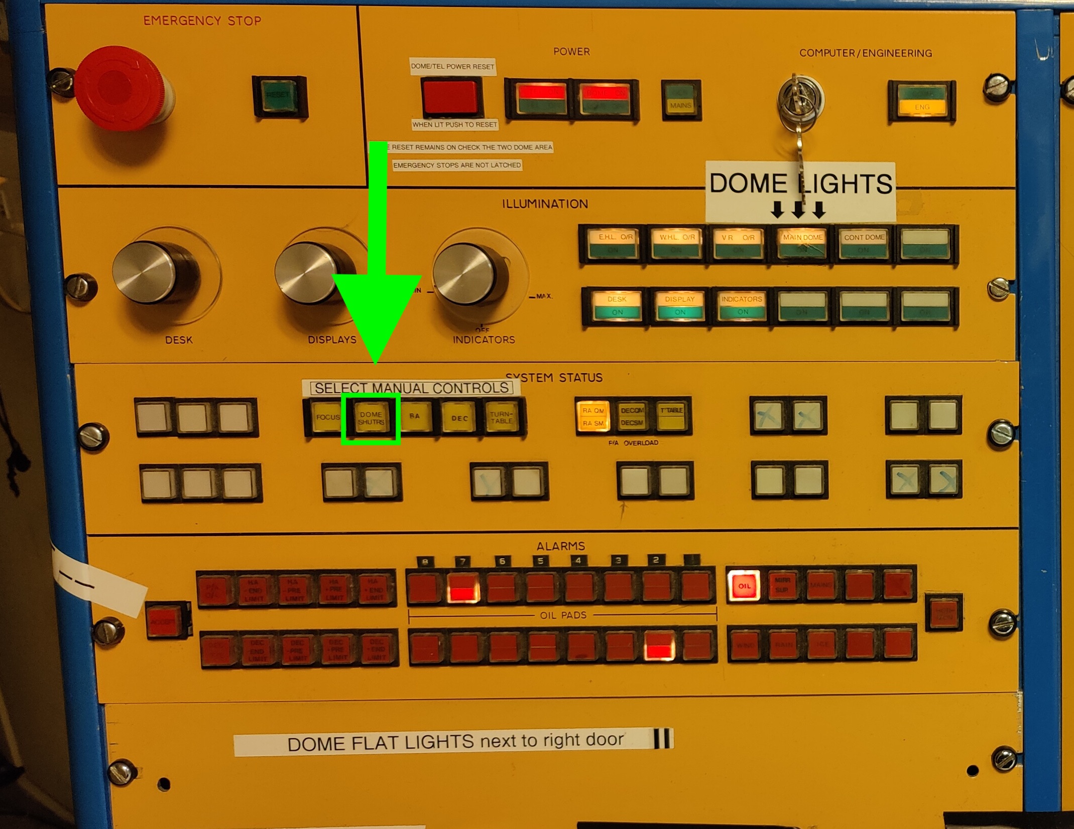
- Push the yellow button under SELECT MANUAL CONTROL, labelled DOME SHUTRS to get the control of the shutters.
- On the engineering rack, under LOWER SHUTTER, push the RAISE MICRO button until the MAIN OVER TRAVEL light underneath goes off.
- Follow by pushing the RAISE MAIN button; while raising, you will hear bangs caused by the segments of the shutter catching the next one. Keep the button pressed until you hear the motor stops. This takes approximately 30 seconds.
- Then press RAISE MICRO button again for a few seconds until the lower shutter completely fits with the upper shutter.
- Release the DOME SHUTRS button, otherwise the dome will no longer track the object.
- Go to the dome with a torch and check that the shutters are properly opened, so that there is no gap between the upper and lower shutters.
- Open the mirror petals.
You can now observe below 33 degrees elevation.
Remember to bring the lower shutter down again when you go to a new source above 40 degrees elevation. To do this:
- Close the mirror petals to protect the telescope mirror.
- Select manual control as before with the DOME SHUTRS button.
- Push the LOWER MICRO button to start lowering the lower shutter. Keep the button pressed for approximately 10 seconds.
- Push the LOWER MAIN button to bring the shutter down as far as it goes.
- Push the LOWER MICRO button to fully lower the shutter. Keep the button pressed for approximately 10 seconds to be sure.
- Release the DOME SHUTRS button, otherwise the dome will no longer track the object.
- Open the mirror petals.
| Note: If the bottom shutter is not fully lowered, then the upper shutter will not completely seal the dome at the top and rain/wind will penetrate into the dome. |
Back to Top
23. Observing targets moving at non-sidereal rates
If you want to observe a target that moves at a non-sidereal rate (e.g. a solar system object such as a comet or an asteroid) the TCS needs to be told to track at a different rate from sidereal.
The differential rates in RA, dRA (in seconds/second) and Dec, dDec (in arcseconds/second) in the Equatorial Coordinate System, should have been previously calculated for all times during the night when observations might be wanted, as well as the RA and Dec at these times.
The differential tracking rates are then input to the TCS using the following sequence of commands:
USER> gocat {object_name}
USER> diff_rates dRA dDec
USER> next
Check that the TCS shows that a differential tracking rate has been applied: a line near the top of the TCS Display should say "Differential Rate dRA dDec".
|
There is no autoguiding mode available for IDS using differential rates. Corrections need to be applied manually to keep the object within the slit (every 2-3 minutes), using the HANDSET. |
To return to sidereal tracking (e.g. for standards) issue the TCS command:
USER> diff_rates 0 0
USER> next
NOTE: The TCS requires the differential tracking rates to be expressed as:
-
dRA = d(RA)/dt [in SECONDS/sec]
dDec = d(Dec)/dt [in ARCSECONDS/sec]
Sometimes, ephemerides are given as:
-
dRA = d(RA)/dt x cos(Dec) [in ARCSECONDS/hour] (1)
dDec = d(Dec)/dt [in ARCSECONDS/hour] (2)
Thus, to transform these for TCS input, compute:
-
dRA = (1) / (3600 x 15 x cos(Dec)) [in SECONDS/sec]
dDec = (2) / 3600 [in ARCSECONDS/sec]
In case the ephemeris server gives you two options, chose "coordinate motions"
instead of "sky motions", so you don't have to divide dRA by cos(Dec) anymore.
Back to Top
24. Observing Commands
Here follows a list of the most commonly used commands throughout the night. See also the ULTRADAS Dictionary for commands related to exposure definition and CCD parameters settings.
Remember that the lower shutter starts vignetting at ZENITH DISTANCE
>57 degrees (ELEVATION <33 degrees) - the system does not warn you!
If you need to observe at ZENITH DISTANCE > 57 degrees, please follow
the instructions described in Section 22.
talkerBellINT command
The talkerBellINT command produces a beep from the INTICS computer. It is useful to use when you want to be warned that a previous command was finished, for example:
SYS> run 1800 ; talkerBellINT
will produce a beep after the exposure of 1800 sec has finished the readout.
It is case sensitive so it should be written with the capitals (as shown in the example above). Just in case, check it before using it to adjust the volume on the speakers to hear it properly. To check it just type:
SYS> talkerBellINT
Science exposures
| SYS> run 1200 "XXXXX" | Exposes for 1200 seconds and name the image XXXXX. Note that if you don't specify a comment, the observing log automatically sets as a comment, the target name written in your catalogue. |
| SYS> multrun 3 120 "XXXXX" ; talkerBellINT | Takes 3 consecutive exposures of 120 seconds each. The talkerBellINT will beep after the sequence is finished. See talkerBellINT command section above. |
At the end of the exposure, if you want to move to another target:
| SYS> guide off | Stops guiding. |
| SYS> guide on | Recovers the guiding in the same guide star if telescope is not moved. |
If you won't be using the acquisition camera for a while, press Stop in the "SDSU Autoguider on AG0" to stop readout of acquisition camera.
Interrupting exposures
There are three commands that
- The command abort terminates an observation started by run and similar commands. The observation is not saved to disk. If the run was part of a multiple-exposure sequence (started by multrun etc.), abort terminates the current run and all subsequent runs of the sequence.
SYS> abort
- The command finish terminates an observation started by run and similar commands.The observation is saved to disk as if the full integration time had expired. If the run was part of a multiple-exposure sequence (started by multrun etc.), finish only alters the current run. Other runs in the sequence carry on.
SYS> finish
- The command newtime alters the demanded exposure-time of the observation currently in progress. If the new demanded time is less than the time already exposed, then the exposure ends immediately as if the command was finish.
SYS> newtime {new-exposure-time}
If you were running a script that will execute more ICS commands than taking exposures (e.g. turning on calibration lamps, setting the calibration mirror, etc) you have to terminate the script. To finish the script you can try:
SYS> <Ctrl>-c
If this does not work then you can do:
SYS> <Ctrl>-z
Then check the suspended jobs by:
SYS> jobs
and kill your script via:
SYS> kill %n
where n is the job number (not the PID!).
Sometimes just kill %n is not enough. In this case you should use kill -9 %n.
Back to Top
25. Observing scripts
The observers could use their own observing scripts to observe a given sequence,
given an object (ex. obj1) was previously defined in the catalog, using standard observing
commands. First, from your laptop you have to FTP your script (example johnscript) to the INT system:
sftp intobs@intdrpc1Second, you have to change directory to:
sftp> cd /home/intobsThird, you have to put your script there:
sftp> put johnscriptFourth, change its permission for execution there:
sftp> chmod 555 johnscriptFinally, from the INT ICS terminal in the same /home/intobs/ directory, you can run the script by simply entering its name at the prompt, namely:
SYS> johnscript
Back to Top
26. Examining Data
Note:
If you plan to reduce your data on the INTDRPC1 remember that you must
not operate on the images stored in the /obsdata directory (in
particular, NEVER move or delete the image files). You can create
a directory in the /scratch folder (e.g. /scratch/inta/20111005) or in
the /reduction/local folder on INTDRPC1, and copy the images there to
proceed with your own data processing. This should not be a substitute
for backing up your data as these files are periodically wiped
clean.Data format
In IDS data from Red+2 and EEV10 detectors the y-direction (detectors columns) corresponds with the dispersion direction while the x-direction (detector rows) with the spatial direction.In Red+2, the wavelength range in the images goes from blue to red. Lower y-pixel positions correspond to lower (bluer) wavelengths and higher y-pixel positions correspond to higher (redder) wavelengths. For the EEV10 this is inverted, hence lower y-pixel positions correspond to higher (redder) wavelengths and higher y-pixel positions correspond to lower (bluer) wavelengths.
The spatial x-direction remains the same in both detectors.
IDS images are MEF files. The full image header and the spectrum are on the extention [1].
Images from AG0 acquisition camera, are not science grade images and they will not have a complete header as the IDS images. These images will be listed in the night log and stored in the directory of the night together with the science IDS (Red+2 and EEV10) images.
Manual image check with IRAF
First, close any active IRAF sessions on the INTDRPC1 computer. Then issue the command iraf in a terminal window. This will open an xgterm window, a ds9 window and execute IRAF automatically.
The IRAF interface on the Data Reduction System (INTDRPC1) is used to examine the data. From the IRAF prompt, make sure you are in the correct directory (today's directory can be found at the bottom of the udas_camera_mimic display on the ICS) or change to it by:
ecl> cd /obsdata/inta/yyyymmdd
where yyyymmdd is today date in the format year-month-day.Use the following IRAF command to display the image: ecl> display r242645[1] 1 ; imexam
It loads the 2D spectrum of image number r242645 in the ds9 window. Note that for Red+2 detector images, the spectral dispersion goes from blue (lower y-pixel positions) to red (higher y-pixel positions). For EEV10 detector images, spectral dispersion goes on the opposite way, from red (lower y-pixel positions) to blue (higher y-pixel positions). The
Useful imexamine key commands are listed below. The letter has to be typed:
- 'j' for Gaussian fit along a line (spatial direction)
- 'k' for Gaussian fit along a column (dispersion direction)
- 'v' for vector cut; click start and end
- 'c' for column cut
- 'l' for line
- 'e' for elliptical plot
- 's' for surface plot
- 'm' to obtain pixel statistics on section around cursor
- 'r' for radial profile
- 'q' to quit imexam
For a complete imexamine help:
ecl> help imexam
Checking the data quality
Before observations, specially at the beginning of each run, it is important that observers make a quality check of their data:- Take an arc with a slit width narrow enough (1 - 1.5 arcsec), display the image in IRAF, and check the FWHM of several single arc lines with imexamine and 'k' letter typed over each arc line. Check the final FWHM and compare it with the expected FWHM for the slit projected to 2 pixels at detector in IDS Gratings tables (7th column). The final FWHM differs slightly for each detector, and also for each grating due to the grating magnification. For example for Red+2 detector, R150V grating and 1.03 arcsec slit width, FWHM should be around 2 pixels for each arc line. You should find the same FWHM, 2 pixels, for Red+2 detector and H1800V grating, but with 1.4 arcsec slit width. Make sure that your measurements meet expectations. An example of the good and bad spectrograph focus with a slit width of 1.5 arcsec, grating R400V and EEV10 CCD can be seen on this picture.
- On a point source exposure (for example of a standard star or a star used for focusing the telescope, after the telescope focus is set to the best value), check also the spatial profile of your spectrum. Display the image in IRAF, and with imexamine use 'j' letter typed over the spectrum. Measure the spatial profile close to the center of the CCD, that is around pixel y=2100, to avoid regions close to CCD edges where the optical quality is worse. Check that the final profile is Gaussian (no double peaks or asymmetries present), and also that the FWHM of spatial profile agrees roughly with the seeing on site. In general the seeing at INT is worse than the seeing at WHT DIMM, which is measured at different site, with a different technique and close to Zenith. The seeing is typically around 0.5 arcsec higher at INT than at WHT DIMM. The spatial scale on IDS with Red+2 detector is 0.44 arcsec/pixel, and with EEV10 detector 0.40 arcsec/pixel.
- If you find that FWHM of arc lines is much larger than expected, or your spatial profile is not Gaussian, it is likely that the spectrograph set-up has to be corrected. Ask your support astronomer for help.
Quick-look spectrum extraction
Note: To use the ids_ql task first copy the required data to a scratch area, e.g. /scratch/inta/"directory".You can run the IDS quick-look script at IRAF as follows
ecl> ing
ecl> ids
ecl> ids_ql rxxxxxxx zzz
where the image name is given without the '.fit' extension and zzz is the approximate x position of the spectrum on the CCD (not dependent on binning). The script carries out an optimal extraction (takes ~ 1 sec) and displays the spectrum in the iraf graphics window using splot, so all the usual keystrokes are available. No wavelength calibration is provided.
Note that the Signal-to-Noise you calculate for your spectrum might be under-predicted with respect to the estimation from the Exposure Time Calculator. It might needs some update including new throughput test results. Last throughput test was performed in 2011 when commissioning the Red+2 detector. It has been a longer time since last throughput tests was carried out for EEV10. The reflectivity of the optical surfaces might have been degraded over the years. The reflectivity degradation might affect in a different way at different wavelength ranges and resolutions (gratings).
Back to Top
27. Closing down at the end of night
- Check that the acquisition camera AG0 and the autoguider are not reading out (press Stop in both windows).
- Push the DOME VENT FAN STOP button to turn off dome ventilation. The red light will go on when ventilator is stopped.
- Push and hold the MIRROR COVER CLOSE button. Check the mirror petals close fully (the light will also change from red (open) to green (closed)).
- Bring the Telescope to zenith and the rotator to a convenient position
by typing:
USER> park zenith
USER> rotate sky 0 - During winter, in case of possible snow or ice, rotate the dome to 212 degrees:
USER> dome 212
- When in the TCS info screen the telescope appears as STOPPED, switch the TCS to engineering mode
by typing:
USER> eng
The ENG/COMP push button should now be illuminated with a yellow light.
- On the Engineering Rack, close the dome shutter pushing LOWER MICRO until you hear a 'clunk'. Then push LOWER MAIN until the shutter stops
moving. To fully close the dome shutter, push LOWER MICRO again until the shutter stops moving. If the lower shutter is open, it must be closed and lowered before the upper shutter.
- Turn off OIL PUMP from the engineering rack.
The light will be green when oil pump is off.
- Fill the IDS cryostat following the same procedures as at the start of the night. Leave the telescope parked at zenith.
Back to Top
28. Closing Down in a Hurry
If it starts to rain/snow, the humidity rises above 90% or the winds above 80km/h you will
be forced to shut down in a hurry. If this is the case:
- FIRST OF ALL: Close the mirror petals
Push and hold the MIRROR COVER CLOSE button. Check the mirror petals close fully (the light will also change from red (open) to green (closed)).
- Close the dome
-
Select manual control pressing the DOME SHUTRS button on the Engineering Console.
- If the lower shutter is up, it must be lowered before closing the upper shutter:
Push on the LOWER SHUTTER panel the LOWER MICRO button for a few seconds. Then LOWER MAIN until the lower shutter stops moving. Finally push the LOWER MICRO button again to fully lower the shutter. Keep the button pressed for approximately 10 seconds to be sure. - Close the upper shutter:
On the Engineering Rack, close the dome shutter by pushing on the UPPER SHUTTER panel LOWER MICRO until you hear a 'clunk'. Then push LOWER MAIN until the shutter stops moving. To fully close the dome shutter, push LOWER MICRO again until the shutter stops moving. - Release the DOME SHUTRS button.
Note: If the bottom shutter is not fully lowered, then the upper shutter will not completely seal the dome at the top and rain/wind will penetrate into the dome.
-
Select manual control pressing the DOME SHUTRS button on the Engineering Console.
- Stop the current exposure and read out.
Break out of the command and return the SYS prompt by doing, on the ICS window:
SYS> <ctrl-z>Then type:SYS> finishIf you were using a 'mult' command then the command finish will not stop the remaining exposures of the sequence. The sequence must be aborted with the command abort:SYS> abort - Close the south doors if they are open.
- Park the telescope using the command:
USER> park zenith - Turn off the oil pumps. Do not forget to turn them back on before you move the telescope again.
- Shut off the fans.
- If abandoning the telescope due to bad weather then:
IMPORTANT NOTE: For safety reasons, if the observer decides to leave the INT telescope anytime during the night (between sunset and sunrise) he/she should ensure to call to the WHT telescope to inform this to the WHT TO.
- Check/perform all the steps of the procedure Closing Down at the End of the Night.
- Fill in a fault report with the time you filled IDS cryostat so that the Operations Team can refill it first thing in the morning.
- If abandoning due to high humidity turn the alarm off (middle setting) to prevent it sounds during the whole night.
If the telescope is shut down for a long period of time then:
Back to Top
29. Saving Data
Observing data can be saved either on DVD,
directly to your laptop or hard-drive. You only need to write your copy
disk. DVDs can be burnt
on either of the two Linux public computers in the control room
(INTDRPC1 and INTDRPC2).
Recording data on DVDs:
Please refer for details to the following document (also shown on the wall to the right of INTDRPC1):
http://www.ing.iac.es/Astronomy/computing/recording.html.
Direct to Laptop:
Data can be transferred directly to your laptop through
the INGEXT network. This can be done file by file using the scp command
from your laptop:
$> scp intguest@intdrpc1:/obsdata/inta/yyyymmdd/r{number}.fit /your/directory
Of
course the * can always be used as a wildcard.
Alternatively the rsync command can be used to copy all the files from
the directory on intdrpc1 to a directory on your laptop. Running the
command another time then updates your laptop's directory only with the
new data. From your laptop type:
$> rsync -av intobs@intdrpc1:/obsdata/inta/yyyymmdd/ /your/directoryThe password can be found on the screen of the computer. For both actions intdrpc2 can also be used.
Back to Top
30. Creating the Night Log
Fill in the nightlog which is accessed from the
any browser (preferably from the INTDRPC), on this link:
http://obslog.ing.iac.es/. Select INT as the telescope (bottom right part on the webpage) and then, "End-of-night report". It is important to include the breakdown of
observing time: Fill in any downtime that was encountered (bad weather,
technical problems, etc.) and note the time lost. Don't forget to click both "Save to database" and " Save to /home/lplogs".
Back to Top
31. Filling the Operations Logbook
The printed logbook in the control room contains fields which must
be filled out during the night:
CCD cryostats: Initials and local time for filling the CCD(s).
Telescope focus and reference temperature (Internal Temp in the meteorological data screen).
Back to Top
32. Leaving the Building
Before leaving the building, please switch off all major lights in the
control room and in the kitchen area. Check that no electrical devices are
left on in the kitchen, i.e. sandwich toaster, coffee machine, etc.
| IMPORTANT NOTE: For safety reasons, if the observer decides to leave the INT telescope anytime during the night (between sunset and sunrise) he/she should ensure to call to the WHT telescope to inform this to the WHT TO. |
Back to Top
33. Observers handover check
Ready to do it alone? Please check you are familiar with the following tasks:
- checking the quality of your data
- use of intercom and telephone
- safety precautions when using liquid nitrogen
- weather precautions, knowing when the dome must be closed
- observing at zenith distance between 57 and 70 degrees
- opening and closing the dome
- moving the telescope in engineering mode
- starting up and shutting down the observing system
- knowing about the most common faults and how to solve them
- writing/copying your data at the end of every night
- filling in fault reports
- filling in log book in control room
- producing the observing log
- filling in observing feedback form at the end of your run
Back to Top
34. Neutral Density Filters for Calibrations
Neutral density filters in the A&G box dedicated to the lamps.
SYS> compfilta {position}
SYS> compfiltb {position} Where {position} is the requested filter position (0 to 7).
This moves comparison lamp filter A (B) to the position requested. Position 0 is clear, i.e. no neutral density. The command compnd can be used to change both comparison filters A and B to generate the required neutral density. The command change_agb can be used to see the names of the filters currently mounted.
For compfilta
| 0 |
empty (clear) |
| 1 |
0.24 |
| 2 |
0.61 |
| 3 |
0.80 |
| 4 |
1.74 |
| 5 |
3.00 |
| 6 |
Opaque6 |
| 7 |
Opaque7 |
For compfiltb
| 0 |
empty (clear) |
| 1 |
0.33 |
| 2 |
0.50 |
| 3 |
0.89 |
| 4 |
1.20 |
| 5 |
2.10 |
| 6 |
3.30 |
| 7 |
Opaque7 |
Back to Top
35. Acknowledgements
Credits should be
given to the INT Support Astronomers, WHT operators, ING ops-team staff and INT observers who have contributed to improve this manual along the years. Back to Top
| Top | Back |
|
