ISIS imaging-polarimetry user guide
- Basic characteristics
- Afternoon settings and calibrations
- Configuring the telescope
- Acquiring objects and taking data
- Useful information
- Imaging-polarimetry observing commands
Basic characteristics
ISIS can be used as an imaging polarimeter by following these steps:
- replace the grating with a flat mirror (done by a support
astronomer)
- insert a wide calcite analyser and a field mask instead of the spectrograph
slit (done by a support astronomer)
- use the permanently-mounted half- or quarter-wave plates, which are
common to both ISIS imaging- and spectro-polarimetry modes
There are two flat mirrors available (for more information see
below), and so
in principle both arms of ISIS can be used simultaneously. However,
the dichroic causes a
ghost image approximately 11 arcsec away from the real image
due to light reflected off the back surface, as opposed to the front reflective surface, of the dichroic.
This ghost image partly overlaps with the second real image due to
the calcite analyser.
Its intensity is less
than 2% of that of the real stellar image, and therefore it is not
seen for faint targets, for example. In general it is not recommended
to use a dichroic for imaging-polarimetry observations for this reason.
Instead it's suggested to use the dichroic slide fold mirror for blue-arm
observations, and to move the dichroic slide out of the beam for
red-arm observations.
It's possible to use two band-pass filters for observations in each arm.
For the red arm and linear polarimetry, the unvignetted field of view is
roughly 2 by 1.25 arcmin at the centre, and 2 by 1 arcmin at the sides of a field.
For the red arm and circular polarimetry, it
is roughly 48 x 44 arcsec at the centre, and 48 x 26 arcsec at the sides of a field
(see picture below). For the blue arm, the unvignetted field of view is the
same as for the red arm for circular polarimetry, and is less vignetted at the sides by about
15 arcsec for linear polarimetry. See more details here.
The instrumental polarisation measured from the zero-polarisation standard
star is p = 0.07 +/- 0.04 %.
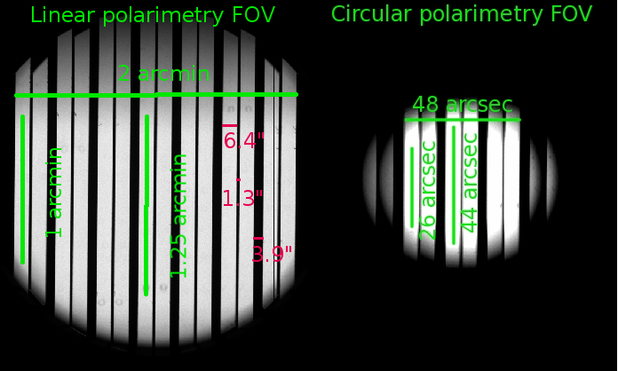
Fig. 1 - The unvignetted field of view and image characteristics for ISIS linear and circular imaging-polarimetry
observations in the red arm. See more details here.
Back to the top
Afternoon settings and calibrations
- Put the calcite analyser in the beam
In order to have the correct information displayed in the ISIS Mimic, Instrument Control Console
and image headers, locate the ISIS Observer tab in the Instrument Control Console, and
in the Slit Unit section choose the "Image polarimetry" option. This will move the
multi-slit unit containing the calcite analyser into the light path, and the image-header
keyword ISISLITU will show IMAGE_POL.
In case you need to move back to the long slit, type:
SYS@taurus> longslit
- Put the retarder plate in the beam
Deploy the half-wave plate for linear polarimetry
or the quarter-wave plate for circular polarimetry in the light path as needed:
SYS@taurus> hwin (for linear) or qwin (for circular)
To take the half-wave or quarter-wave plates out of the beam, type:
SYS@taurus> hwout or qwout
- Insert a filter
You can use two filters for your observations in each arm of ISIS. Filters
are mounted in the following slides: RFILTA, RFILTB, BFILTA and BFILTB.
To use the filter mounted in the BFILTA (or BFILTB) slide
type:
SYS@taurus> bfilta 4 (or bfiltb 4)
Similarly, to use the filter mounted in the RFILTA (or RFILTB) slide type:
SYS@taurus> rfilta 4 (or rfiltb 4)
To remove the filter from the light path, type:
SYS@taurus> bfilta 1 (or bfiltb 1, rfilta 1, rfiltb 1)
- Configure the detector
Define the the read-out speed of the detector:
SYS@taurus>rspeed <camera> <speed>
and the appropriate detector window, using the following values,
which cover the whole field of view and
include an overscan region on the right-hand side (see Fig. 2), as a reference:
For linear polarimetry:
SYS@taurus> window red 1 "[680:2148,1700:2470]"
SYS@taurus> window blue 1 "[695:2148,1580:2440]"
For circular polarimetry:
SYS@taurus> window red 1 "[770:2148,1820:2300]"
SYS@taurus> window blue 1 "[800:2148,1750:2280]"
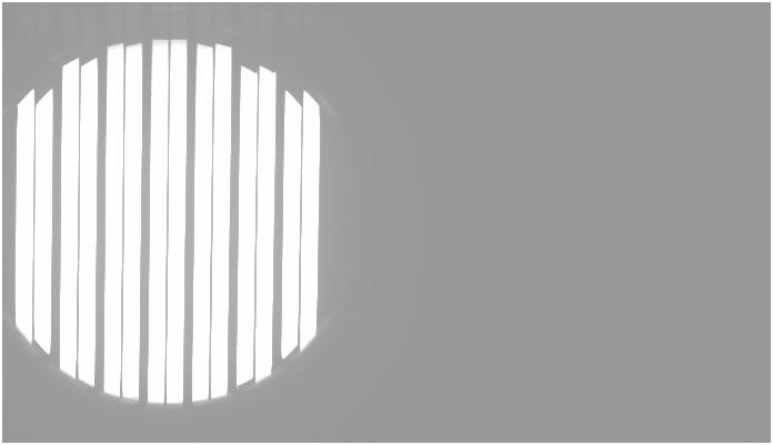
Fig. 2 - This window includes the field and the
overscan columns of the CCD (right-hand side of the image).
The double pattern of slits corresponds to the ordinary and
extra-ordinary image of the comb mask as produced by the calcite analyser.
- Take calibrations
Take the usual set of calibrations described in the
ISIS cookbook, which includes biases and
flat-field exposures. Do not use the internal tungsten lamp for flat fielding: because
of the different optical paths the
stripes projected onto the CCD are narrower when using the internal lamp than when using sky light.
If you are taking dome or sky flat fields, then for linear (circular) imaging polarimetry observations
you can use the half-wave (quarter-wave) plate with continuous rotation of 1 Hz and integer integration
time to depolarise the dome flat-field or sky light.
- Biases
Before taking biases turn off all the dome lights and close the curtains in
the control room.
SYS@taurus> agcomp
SYS@taurus> complamps off
SYS@taurus> multbias red 11 & multbias blue 11 &
- Dome flat fields
In order to take dome flat fields, first ask the telescope operator (OSA) to point the telescope to a suitable
position. Then open the mirror petals:
SYS@taurus> petals open
and direct the light from the dome to ISIS:
SYS@taurus> agslit
Then you will need to find a suitable illumination level to have an integer
integration time. There are in total 5 lamps mounted on the top-ring of the
telescope: lamp number 1 = 9 W, number 2 = 25
W, number 3 = 150 W, number 4 = 500 W and number 5 = 500 W. With the Sloan r
filter in the red arm, lamp number 2 and an exposure time of 10 s have been used in
the past. To turn on lamp number 2 type the following:
SYS@taurus>fflamp 2 on
or to turn on all the lamps:
SYS@taurus>fflamp all on
To rotate the half-wave (quarter-wave) plate with continuous rotation of 1 Hz type:
SYS@taurus>hwprot 1 (or qwprot 1)
Now take some dome flat fields. To take N exposures, type:
SYS@taurus> multflat red (or blue) <N> <int time> "dome flat"
When done, switch off the continuous plate rotation:
SYS@taurus>hwprot 0 (or qwprot 0)
Close the mirror petals and switch off all the lamps:
SYS@taurus>petals close
SYS@taurus>fflamp 2 off
or
SYS@taurus>fflamp all off
Due to the presence of the calcite analyser and mask in
the light path, your flats will look like those in Fig. 1 or Fig. 2.
Instrument flexure (see
here) can cause the exact position of stripes on the image
to move, depending on the telescope's position, and as a result you will not
necessarily have a flat field signal for certain image pixels. It is complicated to
correct for this effect. One possibility is to take flat field exposures
for a range of telescope pointings (e.g., during the night at the relevant pointings, but this of
course uses valuable sky time). Alternatively, you can take flat-fields without
the calcite analyser and mask, but this means that any flat-field signatures due
to e.g., dust on the calcite analyser, is not accounted. The calcite and mask have to be removed
manually, and in order not to interfere with the final instrument set-up, it's
recommended to take flat-fields without the calcite and mask on the
afrternoon preceding the first night of your run.
Please contact your support astronomer in advance of your run if you plan to do this.
- Sky flat fields
For sky flat fields, the telescope can point be parked at zenith. Ensure that the mirror petals
are open and turn on the continuous rotation of the half-wave (quarter-wave) plate:
SYS@taurus>hwprot 1 (or qwprot 1)
SYS@taurus> agslit
Now take some sky flat fields:
SYS@taurus> sky red (or blue) <int time> "sky flat"
During twilight, the sky dims by a factor ~ 2 every 3 minutes.
When done, switch off the continuous plate rotation:
SYS@taurus>hwprot 0 (or qwprot 0)
- Load the catalogue file
If you are planning to observe many targets it's recommended to create your own
catalogue before your observing run to avoid errors in coordinates and to save time.
Please follow the instructions provided
here.
Your support astronomer will help you to place the catalogue file in the
correct path on the
observing system.
Back to the top
Configuring the telescope
- If you are planning to use ACAM during the night, select the focus reference
Sloan r filter when focusing the telescope for ACAM:
SYS@taurus> acamimage slnR
For ISIS set the telescope focus to a value about 0.45 (0.35) mm lower when using the
half-wave (quarter-wave) plate
compared to the nominal ISIS long-slit telescope focus (usually 97.85 mm), e.g.:
SYS@taurus> focus 97.4 (97.5)
for linear (circular) imaging polarimetry mode.
This will enable you to take exposures and
view the star roughly in focus on the CCD and on the slit-view mirror. To ensure that the star is
also in focus on the direct-view mirror, set TVFOCUS 9500 in TVSCALE 5 in ICL.
- Determine the position of the centre of the field mask on the direct-view mirror:
- Switch to agslit mode, point the telescope to a bright star and take
a glance image (7s-10s integration to limit tip-tilt motion) with ISIS.
- Identify the star in the image and ask the TO to apply offsets until the
star appears centred on the central field mask slot.
- Switch to direct view mode using
agcomp and take an image with the direct-view camera.
- Mark the position of the star on the direct-view camera's DS9 display (take
a note of the x,y coordinates in case the marks are erased). This position will be
used to identify and roughly centre subsequent targets using the direct-view camera.
- Refocus the telescope accurately using the usual focus
procedure. First, set up the spectrograph for observing on-sky by typing
AGSLIT and ROT SKY 0. Then acquire a fairly bright star (about 11th magnitude will be fine)
and put it in the centre of the central slot of the field mask found in the previous step. Take a test exposure to
determine the optimal exposure time and use the
FOCUSRUN
command in the
usual way to determine the best telescope focus.
- Refocus the autoguider with the ICL command "AUTOFOCUS 600" (it will probably need reducing by
>1000 from the usual Cassegrain focus because of the
decreased telescope focus).
Back to the top
Acquiring targets and taking data
- To acquire targets you should use the direct-view camera:
SYS@taurus> agcomp
and position the target on the desired slot, as determined by the marks drawn on the TV screen
in previous steps.
- Remove the direct-view mirror:
SYS@taurus> agslit
and check the acquisition by taking a short exposure (or glance) using ISIS. If necessary, do
a final tuning tweak by asking the TO to introduce offsets to
centre the target in the field mask.
- Acqure data using the imaging-polarimetry scripts in /home/whtobs/isis_scripts:
SYS@taurus> linimpolscript <camera> <int time> <title> [nloop] for linear polarimetry,
SYS@taurus> cirimpolscript <camera> <int time> <title> [nloop] for circular polarimetry,
where nloop is the number of loops, and defaults
to one if not specified.
Here are examples of scripts for linear
and a circular
polarimetry which will take 4 and 2 images, respectively, at zero angles
determined by your support astronomer.
Zero angles are different for the red and the blue arm of ISIS, and also may
vary with other spectrograph settings. Your support astronomer will modify the
scripts with the correct zero angles for your run. Fig. 3 is an example of a linear-polarimetry
image of a zero-polarisation standard.
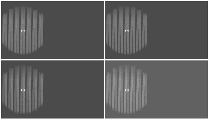
Fig. 3 - Linear-polarimetry observation of a zero-polarisation standard star.
- You can write/save your data following instructions in the
ISIS cookbook.
Back to the top
Useful information
- In the field mask of the calcite analyser (see Fig. 4) there are 7 slots each 6 arcsec
wide, separated by gaps 11 arcsec wide, producing in total 14 images on the CCD (due to the action
of the calcite analyser).
Fig. 4 - The analyser unit for imaging polarimetry.
The calcite is below the dekker field mask (in yellow).
- Image characteristics as measured using blue arm observations, assuming a pixel
size of 0.2 x 0.2 arcsec:
- Each slot through the calcite projects onto the CCD a stripe approximately
6.4 arcsec wide for the ordinary, and 6.4 arcsec wide for the extraordinary, beams,
separated by a gap of 1.3 arcsec.
- There is a projected gap on the detector of approx. 3.9 arcsec between adjacent slots.
- The unvignetted field of view for linear polarimetry is about
120 arcsec in the direction perpendicular to the beams, that is along the
x-axis. Parallel to the beams, that is along the y-axis, the size is ~90
arcsec at the centre and ~75 arcsec at the left-most and right-most slots of the
image. Also, field vignetting for linear polarimetry is asymmetric in
the Y direction, with a gentler cut-off at high Y than at low Y.
- The unvignetted field of view for circular polarimetry is about
49 arcsec in the direction perpendicular to the beams, that is along the
x-axis. Parallel to the beams, that is along the y-axis, the size is ~45
arcsec at the centre and ~27 arcsec at the left-most and right-most slots of the
image.
- Image characteristics (see Fig. 1) as measured using red arm observations, assuming a pixel
size of 0.22 x 0.22 arcsec:
- Each slot through the calcite projects onto the CCD a stripe approximately
6.4 arcsec wide for the ordinary, and 6.4 arcsec wide for the extraordinary, beams,
separated by a gap of 1.3 arcsec.
- There is a projected gap on the detector of approx. 3.9 arcsec between adjacent slots.
- The unvignetted field of view for linear polarimetry is about
120 arcsec in the direction perpendicular to the beams, that is along the
x-axis. Parallel to the beams, that is along the y-axis, the size is ~75
arcsec at the centre and ~60 arcsec at the left-most and right-most slots of the
image. Again, field vignetting for linear polarimetry is asymmetric in
the Y direction.
- The unvignetted field of view for circular polarimetry is about 48 arcsec
in the direction perpendicular to the beams, that is along the
x-axis. Parallel to the beams, that is along the y-axis, the size is ~44
arcsec at the centre and ~26 arcsec at the left-most and right-most slots of the
image.
- Flat fields can exhibit three types of contamination:
- out-of-focus specks, due to dust on the calcite. On occasion, the bigger
specks are visible to the naked eye on examining the calcite physically
- in-focus specks due to dust on the CCD, seen also of course in non-polarimetry configurations
- in-focus hair-like features, which are the rough edges of the dekker slots
- Note that background light, e.g., the zodiacal light, of the dark, moonless sky is polarised
- Observers normally use the detector unbinned or with 2x2 binning. The
readout time for the usual CCD window is 6 s unbnned, and 4 s with
2x2 binning.
-
Since 2016 there are two flat mirrors available for ISIS. The second mirror was used
in the past as a spare mirror for NAOMI (adaptive optics), and therefore has very good
optical quality. When NAOMI was de-commissioned, this mirror was deployed in a
spare ISIS grating holder.
In the red arm, the original flat mirror for ISIS
(henceforth old mirror) and the new mirror have very comparable throughputs.
In the blue arm, however, the old mirror is more efficient (for example, at 3870
(4430) Å the old mirror is 30% (13%) more efficient than the new mirror).
Therefore if both mirrors are to be used it's recommended to use the old mirror
in the blue arm and the new mirror in the red arm.
-
The sky orientations for the red and blue arms are shown
below. When the rotator sky position angle is zero, the
slots of the dekker are aligned approximately east-west.
The acquisition camera (after using the command SYS@taurus> agcomp)
has the same orientation as the blue arm CCD with sky PA = 0 (as
shown on the image below) and also the same orientation as the slit-view
camera (i.e. the same acquisition tool can be used as for normal ISIS
observations).
The field of view of this acquisition camera is ~ 4 x 4 arcmin.
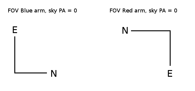
Fig. 5 - The sky orientations for the red and blue arms at sky PA = 0.
Back to the top
Imaging-polarimetry observing commands
Commands to move half-wave (quarter-wave)
plate
SYS@taurus> hwin (qwin), moves retarder plate in
SYS@taurus> hwout (qwout), moves retarder plate out
SYS@taurus> hwp <angle> (qwp <angle>), moves
retarder plate to
requested angle (0-360 deg)
SYS@taurus> hwprot <rate> (qwprot <rate>),
rotates retarder plate at
requested rate (0 - 1 Hz)
SYS@taurus> hwstop (qwstop), stops the rotation of retarder
plate
Continuous rotation of both quarter- and half-wave plates has an automatic time-out
of 12 hours.
Other useful commands
SYS@taurus> longslit, moves the calcite analyser out of beam and
moves to the long slit into the beam
SYS@taurus> mainfiltnd MF-POL-PAR, selects the polariser in the main
ND-filter unit
SYS@taurus> mainfiltnd 1, removes the polariser in the main ND-filter
unit
In case the retarder plates don't move, initialise the half-wave (quarter-wave)
plate by typing:
-SYS@taurus> inhw (inqw)
|


