 | |||
|

| Home > Astronomy > Wide Field Camera > Camera description |
|
| |||
|
| Home > Astronomy > Wide Field Camera > Camera description |
Camera description Contents
Field of view
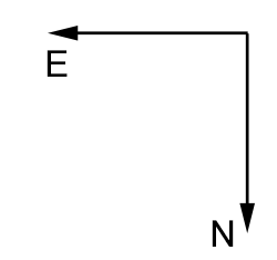
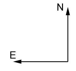
The CCDs of the WFC are arranged on sky as shown in the figure below. North is up and East to the left. The blue arrows show distances in arcminutes from the optical axis (rotator center) shown as a green circle. The orange square is the center of CCD4 which is located at 251 arcsec to the East and 326 arcsec to the North. The unvignetted and 50% vignetted FoVs are shown in green. Given the size of the filters used on the WFC, one only filter placed in the optical path can filter all the photons reaching the science detectors and the autoguider simultaneously.
An overlay showing the WFC CCD mosaic on sky is available with Aladin Desktop. Select File --> Load instrument FoV --> select instrument "WFCINT" and click on SUBMIT.
|
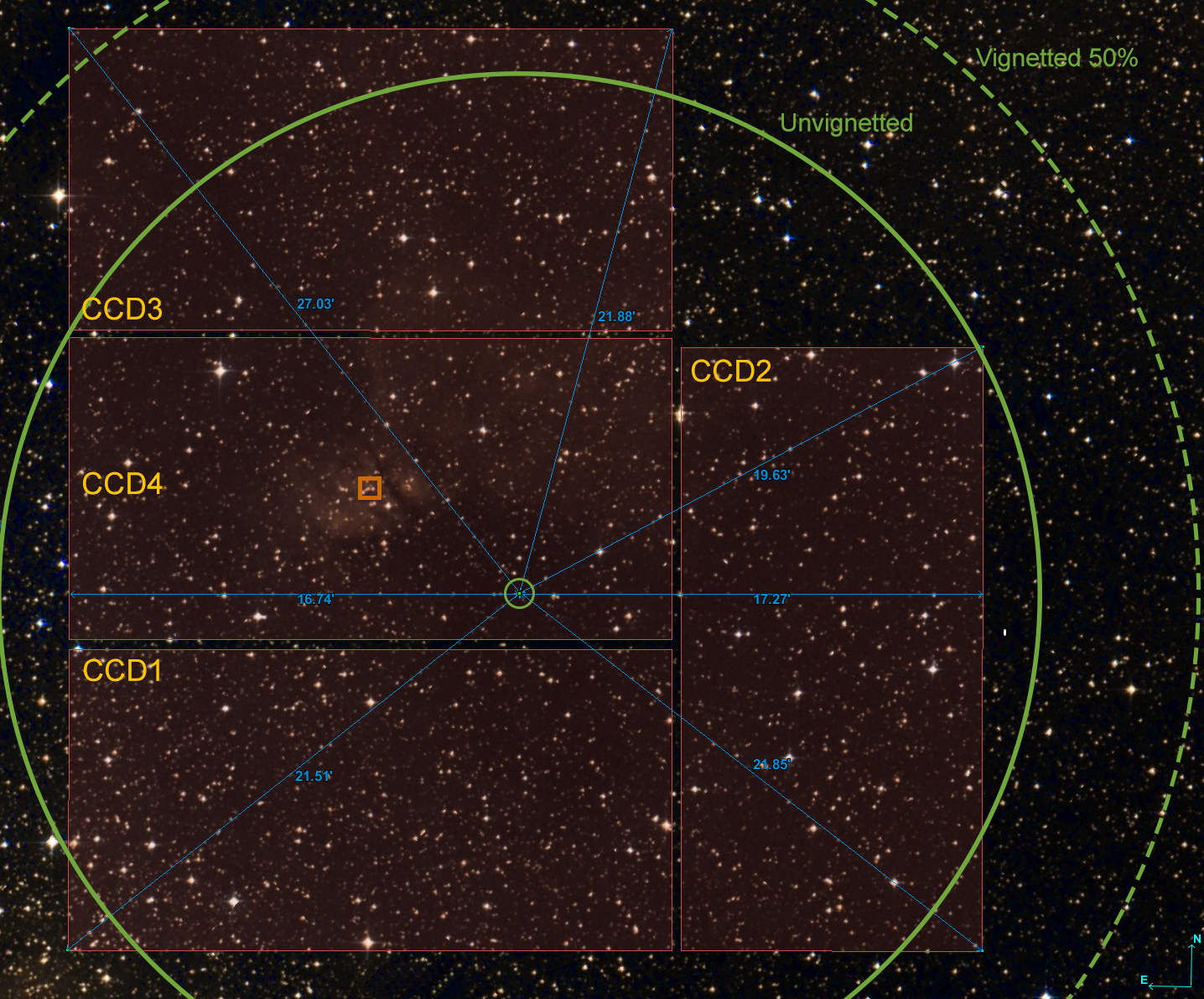
By default the camera FoV is centered on the middle of CCD4 centered on pixel X=1078, Y=2048. CCD4 FOV is 11.2 arminc North to South and 22.5 arcmin East to West. The center of the optical axis (rotator center) is located at X=1839, Y=3036.
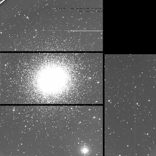 Example of a target centered on CCD4 (M13 globular cluster).
 Example of a target (M81 galaxy) centered at the optical axis (mosaic center) and sky position angle rotated 90 degrees. The detailed arrangement of the CCDs in the camera are shown in this plot of the gaps between image areas. CCDs are not coplanar and the largest separation between CCDs (CCD4 and CCD2) is ~27 arcsec. See overlapping sections below. Readout electronics are shown in red, setting Y=0 in the red bar and X=0 in the red ellipse.
 Orientation
The sky position angle is set to 180° by default. Field orientation on CCDs 1, 3 and 4 is North located at decreasing X values, and East at decreasing Y values. On CCD2 North is at decreasing Y values and East at increasing X values.
To match the sky orientation North up and East left when images are displayed using DS9, one should rotate CCD1, CCD3 or CCD4 images by 270 degrees (select on the top menu of DS9 Zoom => 270°), while CCD2 should be rotated by 180 degrees (Zoom => 180°). If images are displayed with Zoom => 0° (no rotation), then North is to the left and East down on CCDs 1, 3 and 4, and North down and East to the left on CCD2. Read more about INT CCD Scales and Orientations.
Pointing, tracking and guiding
As an average telescope slewing takes 180 seconds and pointing accuracy using the WFC is around 10 arcsec. Pointing is limited to ±6 hours in hour angle. For more information about the accesible sky see INT Pointing Limits and Accessible Sky Area. Telescope starts tracking as soon as it gets to the target.
Guiding preparation takes around 180 seconds and the procedure is described at guiding preparation. The autoguider is a dedicated Loral CCD which is almost coplanar with the science array and it shares with the same filter. Autoguider images are unvignetted, and dithering and guiding is possible. Image data
Images are readout in ~48 seconds providing an area that contains the illuminated pixels (TRIMSEC) and areas that contain only overscan or underscan pixels (BIASSEC). Both sections are written below in the notation [x1:x2,y1:y2] where x1, x2, y1, y2 are in image coordinates, see below for plotted sections. Note that detectors are non-coplanar. See the overlapping sections and section definitions of the CCDs below:  1 ccdname A5506-4 1 chiptype EEV42-80 1 biassec [10:50,5:4190] [10:2150,4105:4190] [2110:2150,5:4190] 1 trimsec [54:2101,1:4096] 2 ccdname A5383-17-7 2 chiptype EEV42-80 2 biassec [10:50,5:4190] [10:2150,4105:4190] [2110:2150,5:4190] 2 trimsec [54:2101,1:4096] 3 ccdname A5530-3 3 chiptype EEV42-80 3 biassec [10:50,5:4190] [10:2150,4105:4190] [2110:2150,5:4190] 3 trimsec [54:2101,1:4096] 4 ccdname A5382-1-7 4 chiptype EEV42-80 4 biassec [10:50,5:4190] [10:2150,4105:4190] [2110:2150,5:4190] 4 trimsec [54:2101,1:4096]Image headers are described in Observation files produced by UltraDAS [INS-DAS-26] document. More information is available in ING FITS Headers and UT in the FITS Headers. Note this issue with the TELFOCUS value. Optical distorsion map
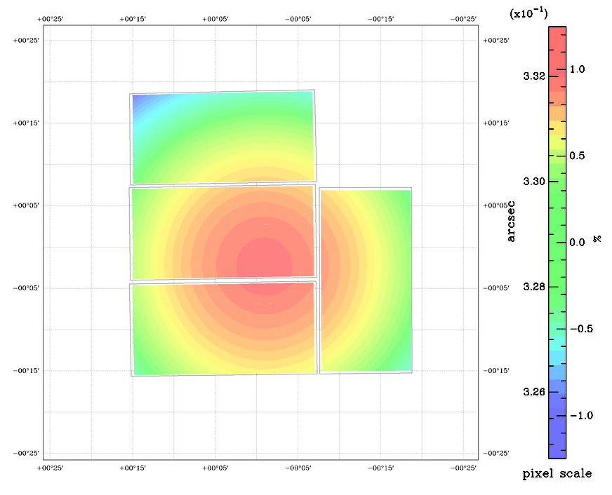
Below is a map of the optical distorsion on WFC's field of view produced by the THELI software. Mean pixel size projected on sky is 0.33 arcsec/pixel.
| ||||||||||
Throughput
The system throughput was modeled by Bell et al. (2012) and it includes the cumulative effects of the transmission of the Earthâs atmosphere, the
reflectivity of the telescope mirror, the transmission of the prime focus corrector optics, the
quantum efficiency of the detector and the filter transmission (filters
u,
g,
z,
i and
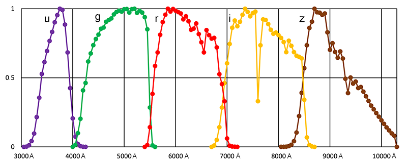
r). The table data also available from Exeter University. Below is the system throughput plotted and normalised to the peak value in each band: 3750Å in u, 5200Å in g, 5850Å in r, 7350Å in i, 8700Å in z.
 Photometric transformations
The same paper of Bell, Naylor et al. (2012)
(2012MNRAS.424.3178B) gives
magnitude and colour differences between the standard Sloan Digital Sky Survey (SDSS) and the
natural INT-WFC photometric systems. The study include the standard SDSS system responses and the
calculated INT-WFC responses, folding atmospheric models through both. Data table available also at this author website. See also their related Bad pixels
The following bad pixel maps
were obtained by dividing two dome flats taken at high and low signal, then running
the IRAF badpix task: Vignetting
The CCD #3 is partially vignetted around one of the detector corners. The following
mask holds 1 for good pixels and 0 for bad pixels and could be used in IRAF to disregard
the vignetted corner. Pixel binning
Binning is possible in all 4 CCDs and windowing on CCD4 only.
WFC binning can be set with the following commands:
SYS> bin 1 1 (1x1 pixels, no binning, by default, pixel scale=0.33")
SYS> bin 2 2 (2x2 pixels, pixel scale 0.66")
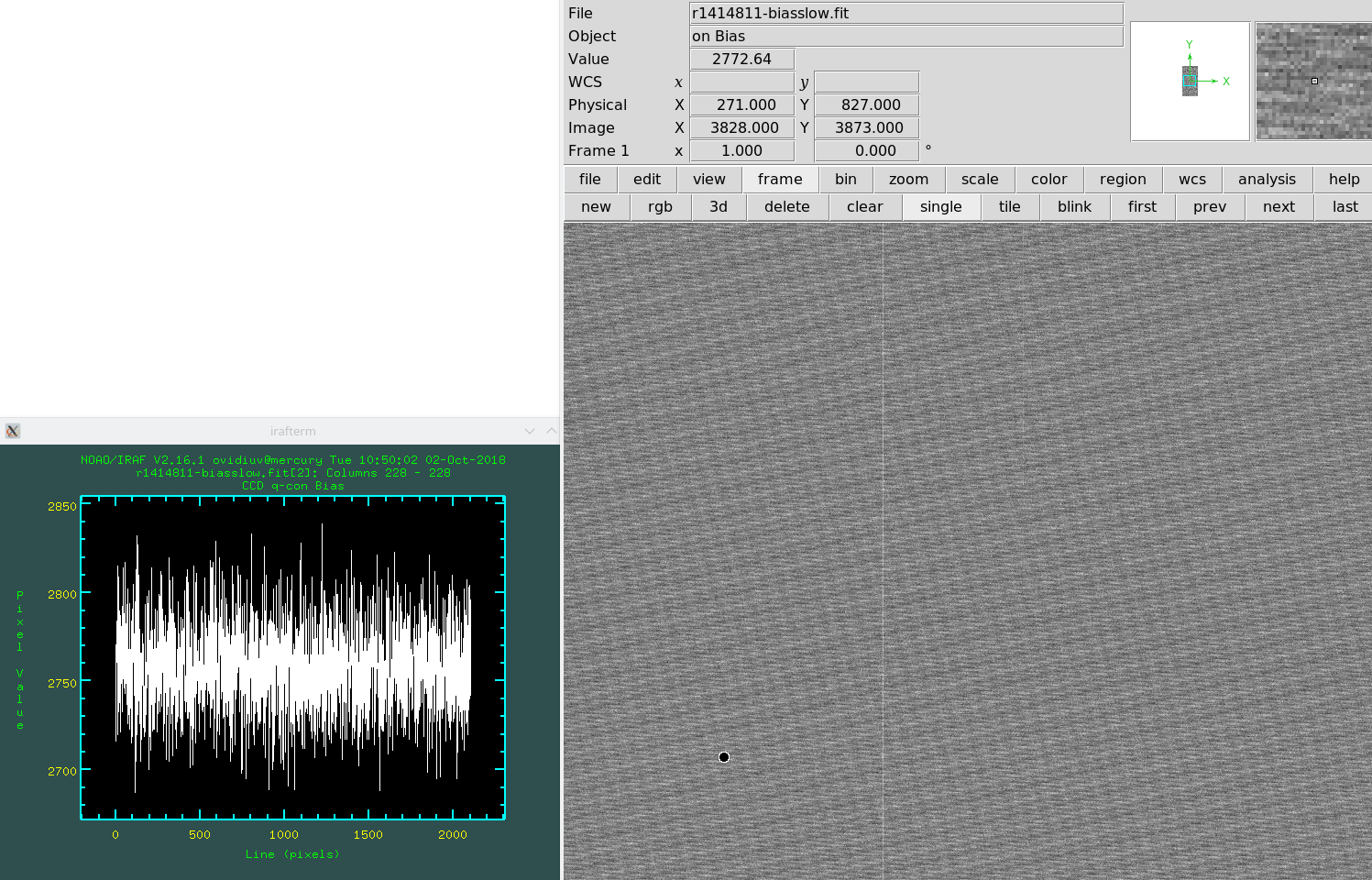
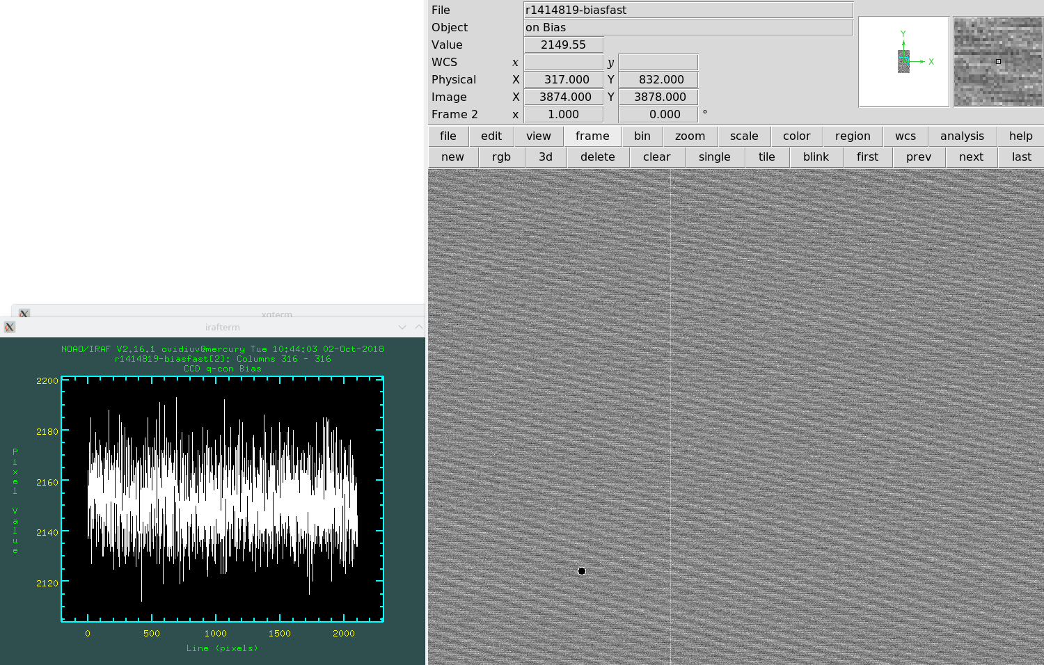
SYS> bin 3 3 (3x3 pixels, pixel scale 1.0") Be aware that binning increases the noise by a factor of 2-5. For the last binning noise and gain values, please check the CCD Quality Control pages. The following plots show examples of binning and noise on CCD2:
CCD2 bin 2x2 slow Readout times for the whole 4 CCD mosaic for different binnings and readout speeds are provided in the following table:
Detector windowing
NOTE: Please do not attempt to use the entire CCD4 as a window (with or without any binning option). This will crash the system.
WFC windowing is possible only on CCD 4. To set binning window [X1:X2,Y1:Y2] (with X and Y coordinates to cover the necessary region (CCD coordinates of chip #4) around the object, type:
SYS> window 4 '[X1:X2,Y1:Y2]'
where (X1,Y1) and (X2,Y2) are the physical corners of the window defined around the object. To disable this window, type:
SYS> window 4 disable
For example, to define a small central 1'x1' window in CCD4, one should use:
SYS> window 4 '[934:1114,1960:2140]'
To define a small central 5'x5' window in CCD4, one should use:
SYS> window 4 '[569:1479,1595:2505]'
While to define a central 10'x10' window in CCD4, one should use:
SYS> window 4 '[168:1988,1190:3010]'
NOTE: By defining a central window, the overscan information is lost. In order to keep the overscan, one should define the window close to the edge of the CCD4 overscan region BIASSEC='[10:2150,4105:4190]'. For example, to define a 1'x1' which includes the overscan, one should use: sys> window 4 '[934:1114,3830:4190]' which includes in Y both the 180-pixel window and the original overscan from Y=4105 to 4190. Once again, CCD4 is the only chip that can be windowed. Moreover, one can define four different windows at the same time on CCD4 (provided they do not overlap), namely window 1, window 2, window 3 and window 4. Remember, these are not related with the four chips. Regarding reading time for different size windows, we measured the following times in slow mode: Whole CCD4 (2154x4200 pix) - 46 sec 10'x10' FOV (1820x1820 pix) - 18 sec 5'x5' FOV (910x910 pix) - 6 sec 2'x2' FOV (360x360 pix) - 4 sec 1'x1' FOV (180x180 pix) - 3 secNOTE: Binning and windowing at the same time will cause the system to crash. |
| Top | Back |
|
