 | |||
|
| Home > Astronomy > ACAM > Spectroscopy with ACAM |
Spectroscopy with ACAM
ACAM provides fixed-format spectroscopy, spectral range ~ 3500 - 9400 A
(~ 3.3 A/pixel).
The slit widths available are 0.5, 0.75, 1.0, 1.5 , 2, 10 arcsec
(or no slit at all).
Observers requiring very wide slits
can deploy one of two focal plane masks with widths
of 27 or 40 arcsec (in the
dispersion direction).
Sections below:
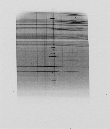
An example spectrum is shown below.

The outer boundary of the figure corresponds to the standard CCD window used: [1:2148,800:3300]. Wavelength increases with y on the CCD, roughly as: wavelength (A) ~ 3.3 * ( y (unwindowed) - 230) [i.e. wavelength (A) ~ 3.3 ( y(windowed) + 570)] or, equivalently: y (unwindowed) ~ (wavelength/A) / 3.3 + 230 [i.e. y (windowed) ~ (wavelength/A) / 3.3 - 570] That is, the dispersion is ~ 3.3 +- 0.1 A/pixel, and unwindowed 1230 < y < 3050 (windowed 430 < y < 2250), the range over which light is detected, corresponds to wavelengths ~ 3300 - 9400 A. For approximate wavelengths of prominent arc lines, see the ACAM CuAr and CuNe arc maps. The approximate (unwindowed) y coordinates of some other useful lines are given below: y y (unwindowed) (windowed) Wavel Line pix pix A 2521 1721 7594 Atmospheric absorption, A band 2305 1505 6867 Atmospheric absorption, B band 2211 1411 6568 Hα 2150 1350 6330 Laser line (used in lab tests) 2009 1209 5896 NaD sky line 1916 1116 5577 OI sky line 1553 753 4366 Hg line of dome fluorescent lamps 1456 646 4054 Hg line of dome fluorescent lampsThe central row of the default window, i.e. y(windowed) = 1250, corresponds to wavelength ~ 6010 A. In the spatial direction, the spectrum runs from x = 335 - 1725, corresponding to ~ 5.8 arcmin (the length of the slits in the focal-plane mask, of which the central 5 arcmin can be illuminated by light from the calibration lamps). The top end of the slit (it's vertical when the telescope points at the zenith) images at the right-hand side of the CCD. The spatial scale is ~ 0.25 arcsec/pixel, as for imaging. At sky PA = 0 (north to the right, in imaging mode), the slit will be oriented north-south (north to the right). (This hasn't always been the case: during the first few months after commissioning, sky PA = 0 rotated the instrument so that in imaging mode, north was up, and the slit ran east-west.) The sky lines (or arc lines) are slightly curved relative to the CCD rows, due to the VPH (and its flanking prisms) being in an f/22 beam, rather than a collimated beam. The sky/arc lines are rotated clockwise relative to the CCD rows (as conventionally displayed) by about 0.26 deg (last measured 2018). The spectrum is also rotated relative to the columns on the CCD, by about 2.0 deg anticlockwise (on a conventional display of the image). On the AUXCAM CCD, the underscan and overscan strips lie at x < 50 and x > 2100 respectively.
Order-sorting filters
The transmitted wavelength ranges, and the parts of those ranges which won't and will be contaminated by second-order light, are:
Filter   Transmitted       Uncontaminated  Contaminated by
         wavelengths                       second-order
         (A)               (A)             (A)

None     3300-9500         3300-6600       6600-9500

GG395A   3950-9500         3950-7900       7900-9500

GG495A   4950-9500         4950-9500       None
The 400-lines/mm transmission VPH (Volume Phase Holographic) grating is modelled to deliver the following resolution R on axis (i.e. with the target near the middle of the slit) as a function of wavelength and slit width:
NB the actual slit widths available are 0.5, 0.75, 1.0, 1.5, 2.0 and 10.0 arcsec - there is no 1.25-arcsec slit. For slit widths < 1 arcsec, the off-axis resolution (i.e. towards the edge of the field) will be significantly poorer than tabulated above, due to aberrations introduced by the optics. In the lab, at a wavelength ~ 5500 A, we have measured on-axis R ~ 900 for a 0.5-arcsec slit, and R ~ 450 (4 pixels = 13 A) for a 1-arcsec slit, consistent with the above predictions. The degradation of spectroscopic resolution with radius is as predicted. E.g at radius 4 arcmin, slits of 0.5 and 1 arcsec deliver the same spectroscopic resolution R ~ 400. The disperser is usually mounted in position 6 of filter wheel 2. It is mounted in Littrow mode (i.e. cemented to prisms which ensure that the diffracted light emerges ~ on-axis). A 500 lines/mm disperser with better throughput in the blue has been purchased, but is not yet commissioned.
Very wide slits
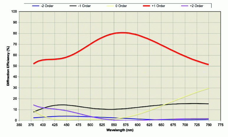
These masks are useful for e.g. exoplanet-transit observers interested in high-accuracy time-series photometry. The VPH grating reduces the throughput relative to that achieved in imaging mode (see the ACAM-imaging page). According to the theoretical-performance data supplied by the manufacturer (Kaiser Optical Systems):
(and extrapolating), the diffraction efficiency of the VPH in first order is 0.55, 0.58, 0.80, 0.70, ~ 0.50 and ~ 0.4, in U, B, V, R, I and Z bands respectively (blaze angle = 5650 A). In addition, light is lost due to reflection at air/glass interfaces (all uncoated, in the currently-installed VPH) and within the material itself, giving a factor 0.78. The net throughput of the grating at the blaze wavelength of 5650 A is therefore 0.80 * 0.78 = 0.62. At 7000 A, the measured zeropoint (AB mag for 1 detected photon per sec per A) is 18.51.
Throughput relative to ISIS
i.e. in the red, ACAM is more sensitive than ISIS/R158R/REDPLUS, but in the blue is slightly less sensitive than ISIS/R158B/EEV12 (the QE of EEV12 is higher in the blue than that of AUXCAM). The numbers above are based on the measured zeropoints of the two instruments, obtained at different times. As a check, near-simultaneous wide-slit observations of a standard star were obtained with the two instruments, during ACAM commissioning. At 7000 A, the throughput of ACAM/VPH/AUXCAM at 7000 A, in photons per sec per A, was measured to be a factor 1.5 higher than that of ISIS/R158R/REDPLUS, consistent with the above. No ghosts have been observed. In particular, a spectrum of 633-nm laser light (almost central on the CCD) shows no ghost lines with intensity > 0.01% that of the main line. Two undispersed light leaks are visible on arc spectra at unwindowed x,y ~ (420, 2860) and (1600, 2860). They are barely visible on the spectrum reproduced at the top of this page. Since these leaks affect only areas near the ends of the slit (2.5 arcmin off axis), they are unlikely to be a problem for most oberving programmes. The cause of the leaks is unknown.
Flexure During a typical half-hour exposure, at any elevation, the flexure is unlikely to cause shifts > 1 pixel in either imaging or spectroscopy mode. However, there will in general be significant shifts on slewing to new targets, so for accurate wavelength calibration, arc exposures should be taken before or after observing each science target.
Repeatability The small shifts between the centre positions of ACAM's spectroscopic slits, when nominally deployed on-axis, are given on the ACAM slit positions page. Arc and continuum illumination for wavelength calibration and flat-fielding are provided by the standard A&G-box calibration lamps. With the CuAr and CuNe lamps both switched on, a 1-sec exposure provides plenty of arc lines covering at least the range 4200 - 9300 A. There are few usable lines at wavelengths bluer than 4200 A. Arc maps for these lamps, when used with ACAM, can be found in La Palma Technical Note 135. If the LIRIS instrument is mounted at Cassegrain (instead of ISIS), the CuAr lamp may not be available. The CuNe lamp alone provides usable lines in the range 5000 - 9100 A, but the lines in the blue are faint, so it's advisable to take two exposures, of e.g. 1 and 15 sec. The fold mirror reflecting light from the calibration lamps illuminates only the central 5 arcmin of the 5.8-arcmin slit. ACAM does not include an atmospheric-dispersion corrector, so spectroscopic observations should be carried out with the slit at the parallactic angle. |
| Top | Back |
|


