Zeropoints
The table below lists the magnitudes measured to correspond to 1 ADU/s
for the given filters, on the given dates. Measurements will change
as the numerous optical surfaces deteriorate and are cleaned.
| Date | J | H | Ks | pupil stop |
|---|
| Sep.02 | 21.4 | 21.7 | 21.0 | OSCA-Obs |
| Apr.03 | 21.5 | 21.4 | - | OSCA-Obs |
| Aug.03 | 21.6 | 21.9 | - | NAOMI-Obs |
Throughput table for INGRID with OSCA
Astrometry
With OSCA the field of view on INGRID is flipped as compared to NAOMI+INGRID
alone.
This means in the case of NAOMI+OSCA+INGRID in GRACE that North is DOWN and East
is to the right. It has been verified that the plate scale on INGRID stays the
same with and without OSCA.
Instrumental features
As coronography increases the dynamic range compared to non-coronographic
observations, the data obtained are also more sensitive to instrumental
features/artifacts. These can lead to false detections and/or a significant
decrease in sensitivity. The main features seen in OSCA data obtained during
commissioning are "blobs" along the x and y axes (see image below).
These are caused by diffraction on the edges of the segments of the
deformable mirror (DM) of NAOMI. They are not a feature of OSCA but with OSCA
these effects become more obvious.
Since these regions are not useful for analysis, the importance of obtaining
images with different sky PAs (rotational dithers) must be emphasised.
The rotation of the field will not change the orientation of the DM pattern.
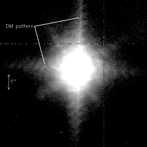
The above figure shows a bright (H ~ 4 mag) behind the 0.65" OSCA mask,
scaled to exaggerate the faint features.
The blobby structure (DM pattern) along the x and y axes is indicated.
The faint lines seen at 45 degrees direction are caused by the secondary
support spider. Note that in this image the OSCA Lyot stop was not installed.
The Lyot stop vanes will remove most of the diffraction spikes by the
secondary spider seen here. Note that while changing the sky PA rotates
all features internal to NAOMI, the diffraction pattern from the secondary
support spider will stay in the same position (although it does move
rotate relative to the N-S axis as the sky rotates).
Note also the quadrant boundaries of the INGRID array. Rotational dithers
will ensure that these areas are recoverd as well.


