 | |||
|

| Home > Astronomy > LIRIS > LIRIS setting-up |
LIRIS Setting-upIn principle setting-up LIRIS for a normal supporting night is quite straightforward. Check that the wheels work, take some flats, biases and arcs; check the wavelength calibration of the latter.LIRIS Polarimetry Auxiliary Elements - MountingThere are three optical elements which can be used when performing LIRIS polarimetric measurements, namely two half-wave plates plus a polaroid. For scientific observations it will be enough to mount the half-wave plates. The polaroid will be mounted only for specialized calibration measurements. These elements are located in the WHT observing floor, in the plastic cube where ACAM filters are, on top shelf. A brief description follows here:
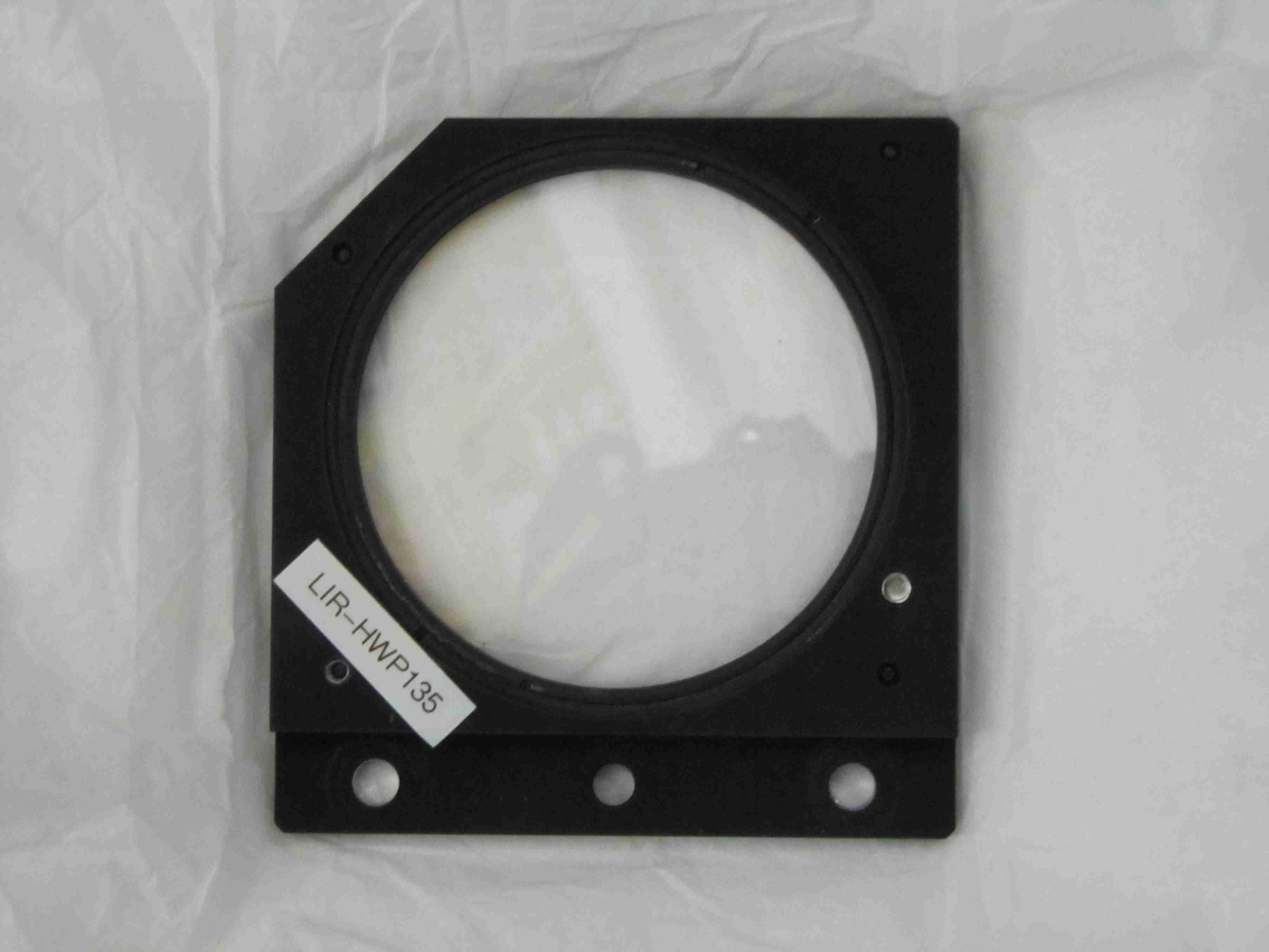
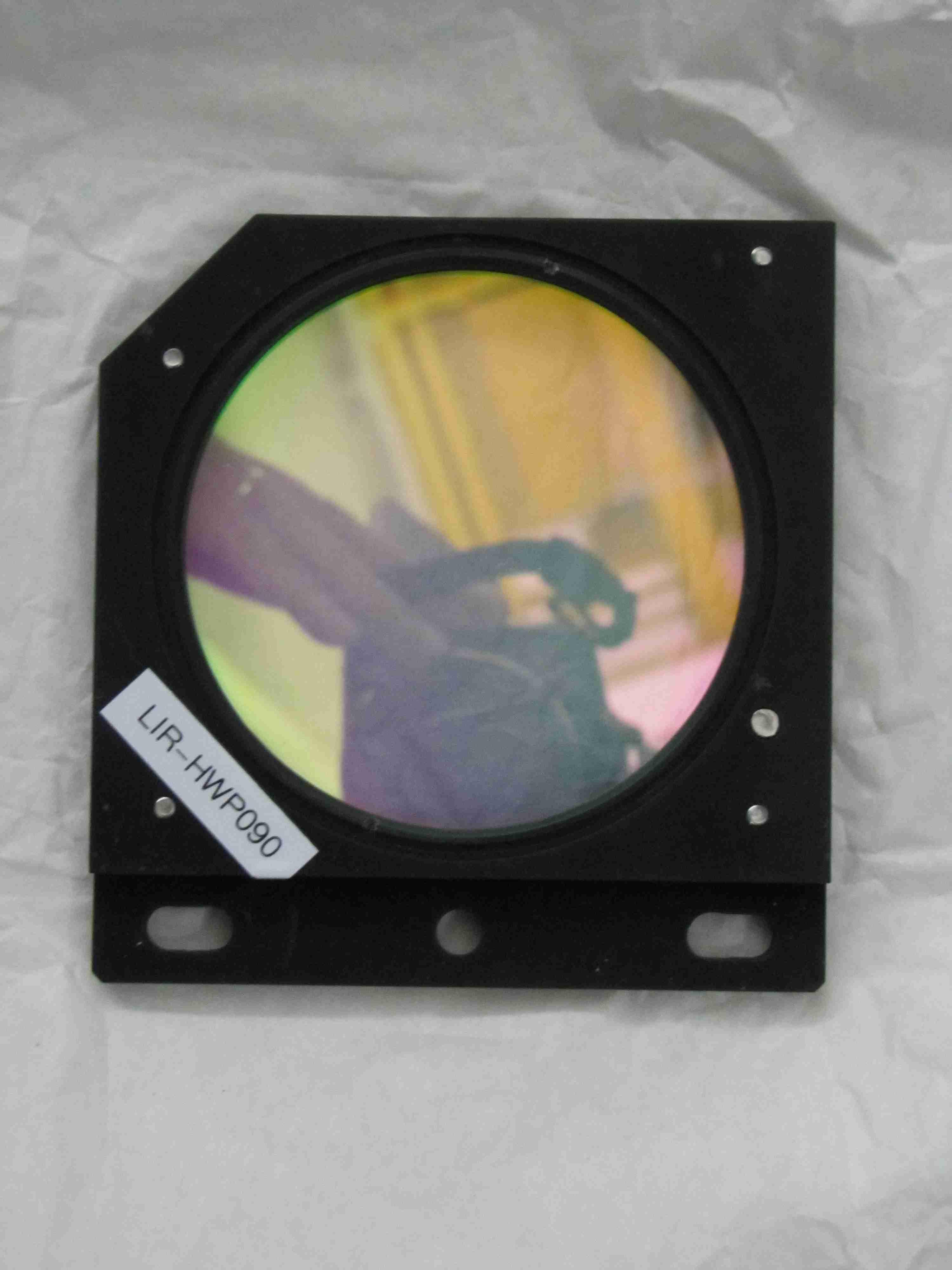
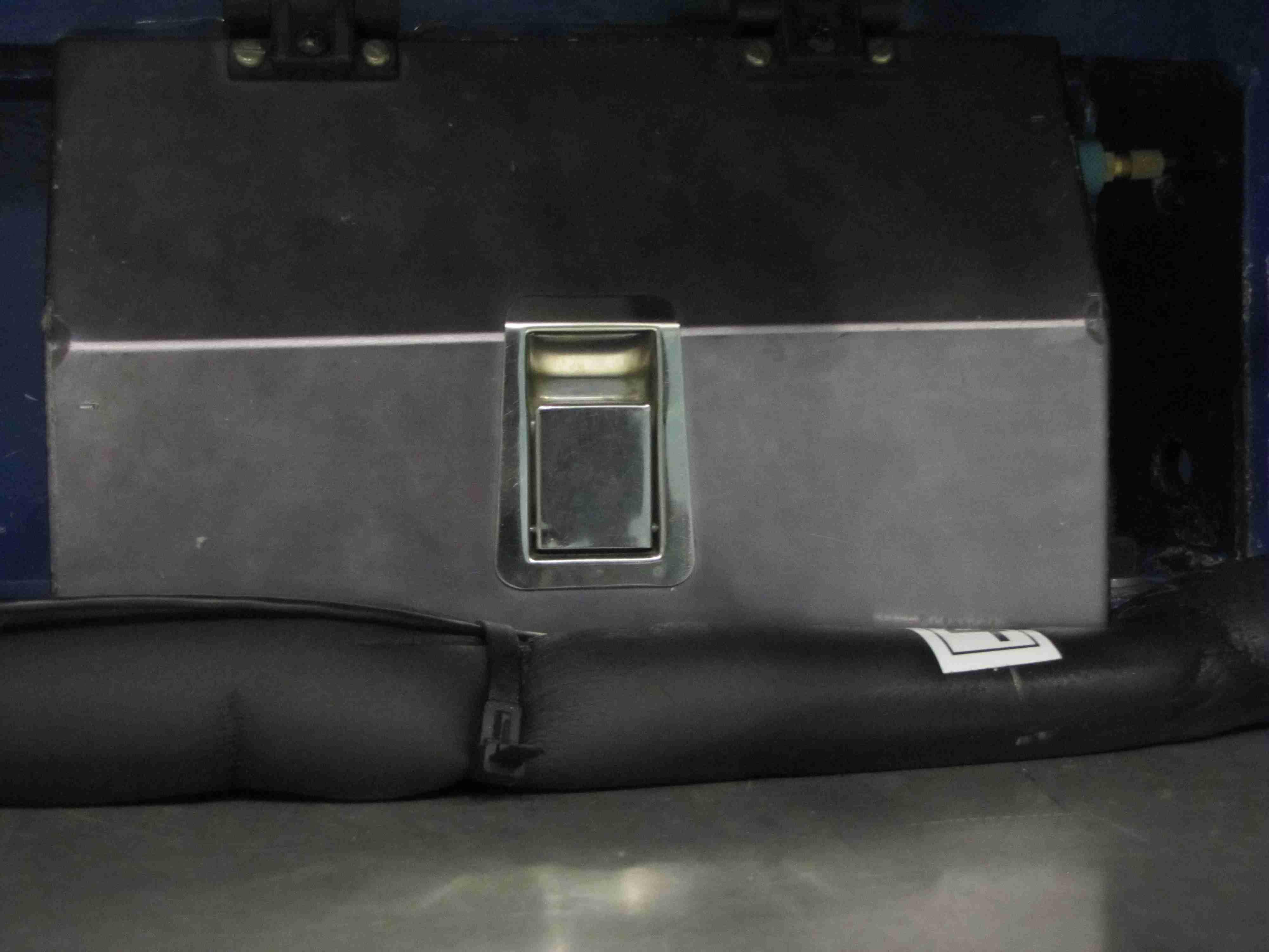
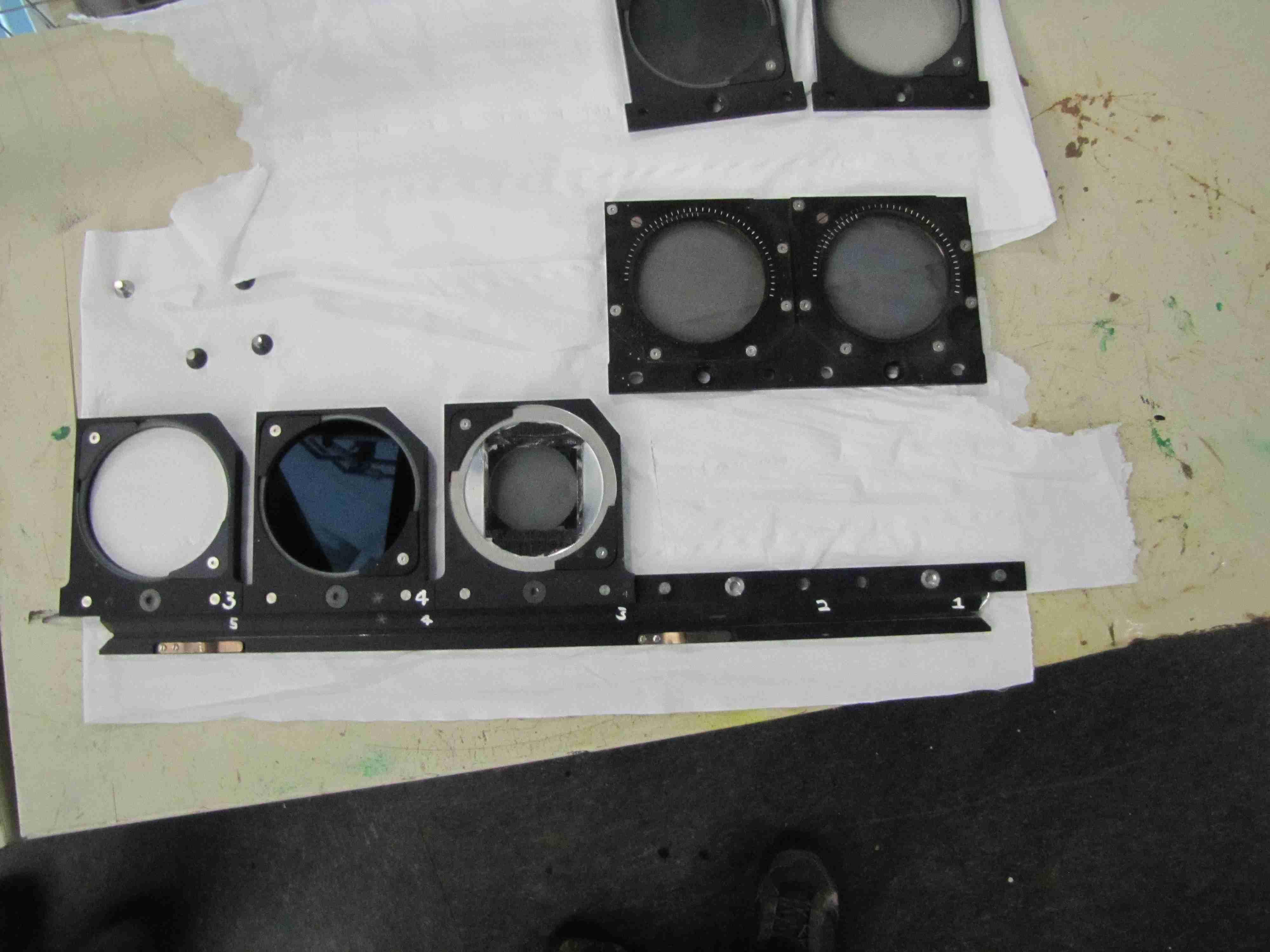
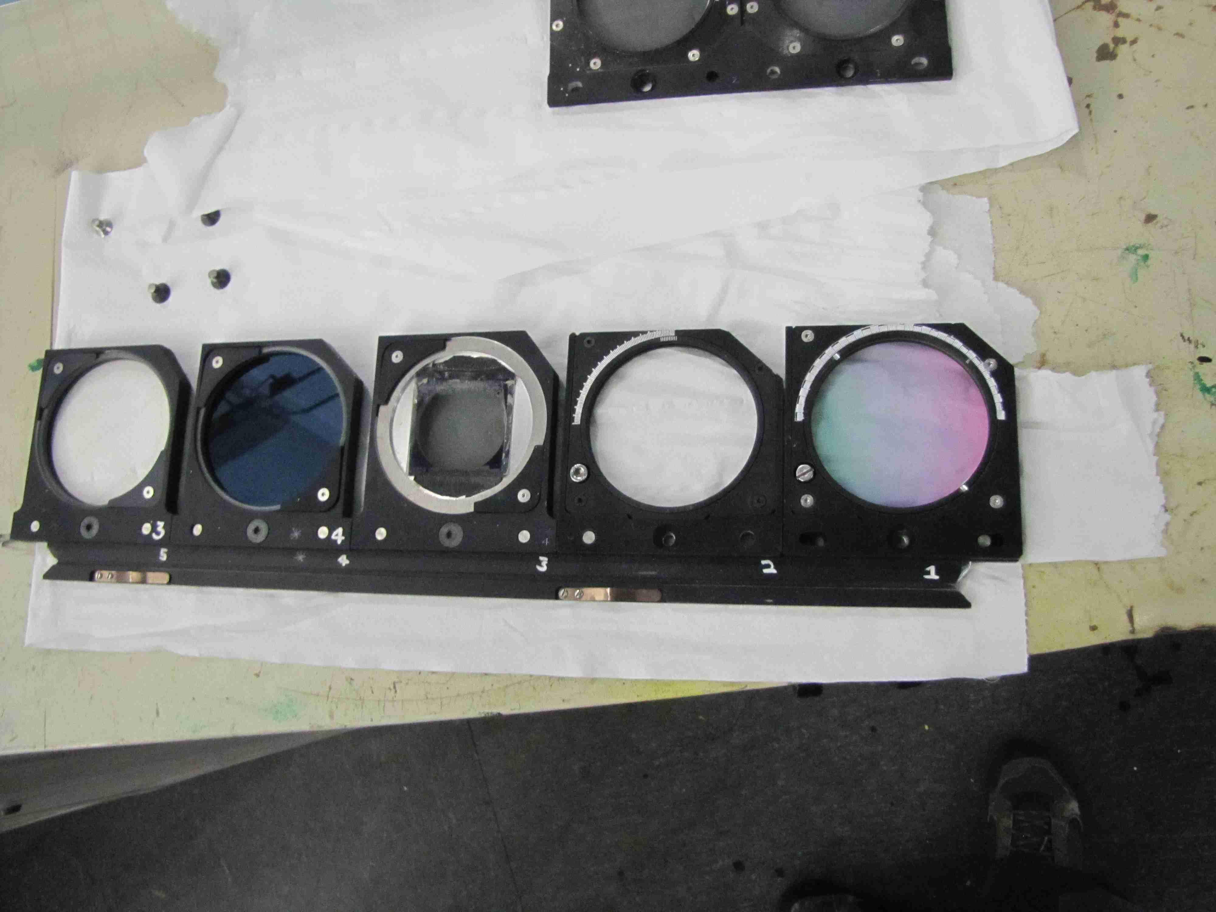
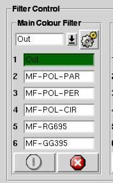
MOUNTING THE HALF-WAVE PLATESThe half-wave plates are mounted in the Main Colour Filter Tray. The auxiliary port is located just above one of the big LIRIS electronic cabinets.1. Before opening the auxiliary port door, go to the Control Room and set the Main Neutral Density Filter tray to any position different that 'Out' (otherwise the other tray cannot be accesed). 2. Then go to the dome and open the auxiliary port door (see Fig. 2). Extract the Colour Filter Tray (the one at the bottom). An allen key (3 mm) is needed, one needs to take out only one screw to get the tray out, the one without the washer. 3. Replace the polarizers used for ISIS calibration (they are mounted in a twin holder) by the two holders with the half-wave plates. LIR-HWPPAR is placed in 1st position and LIR-HWPOBL in the 2nd position (see Fig. 3). An allen key (4 mm) is needed. 4. Put back the tray and update the filter database. See Fig. 5 for their respective associated keywords. 5. Remember to put the neutral density filter back to position 'OUT'.
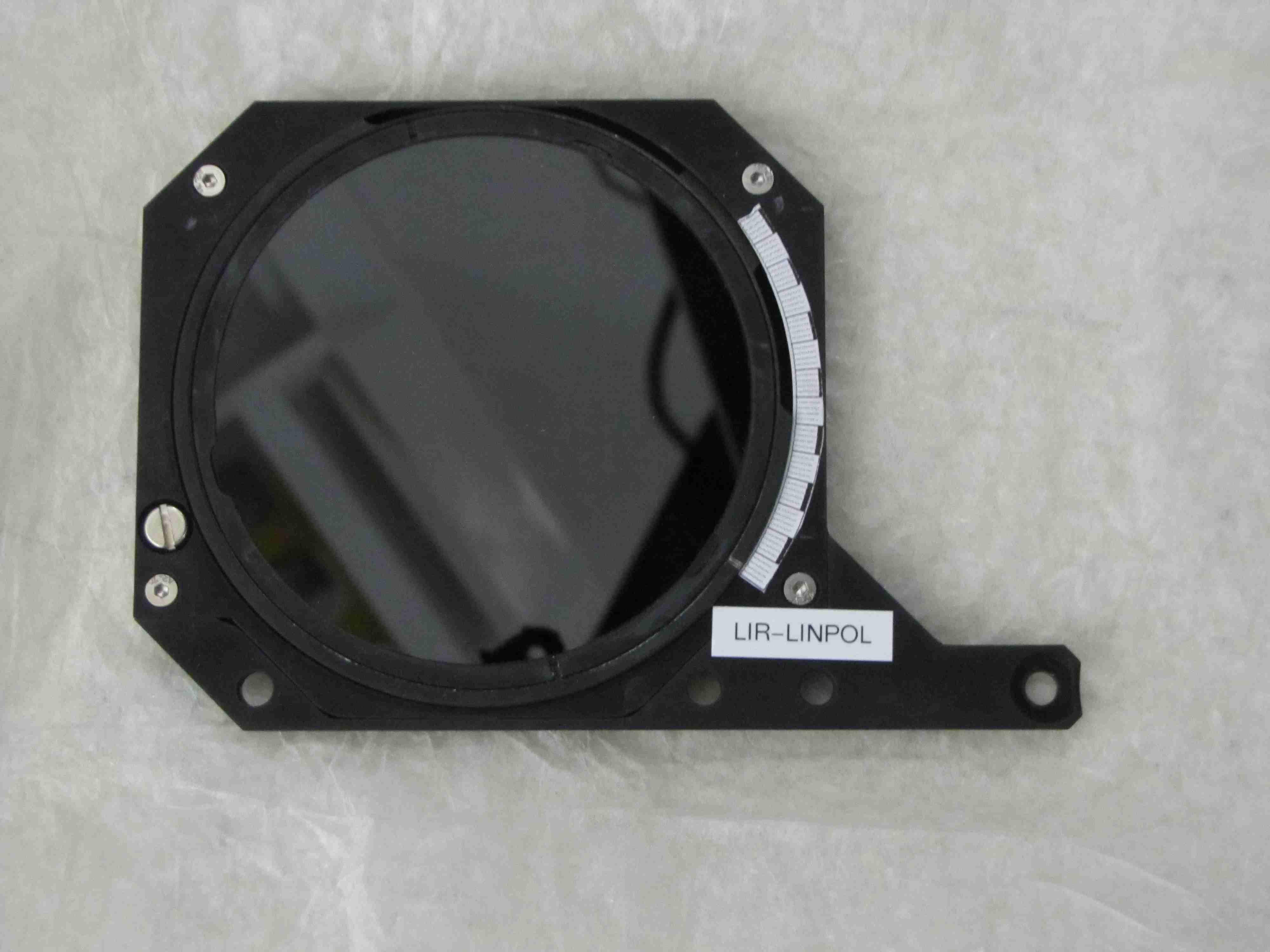
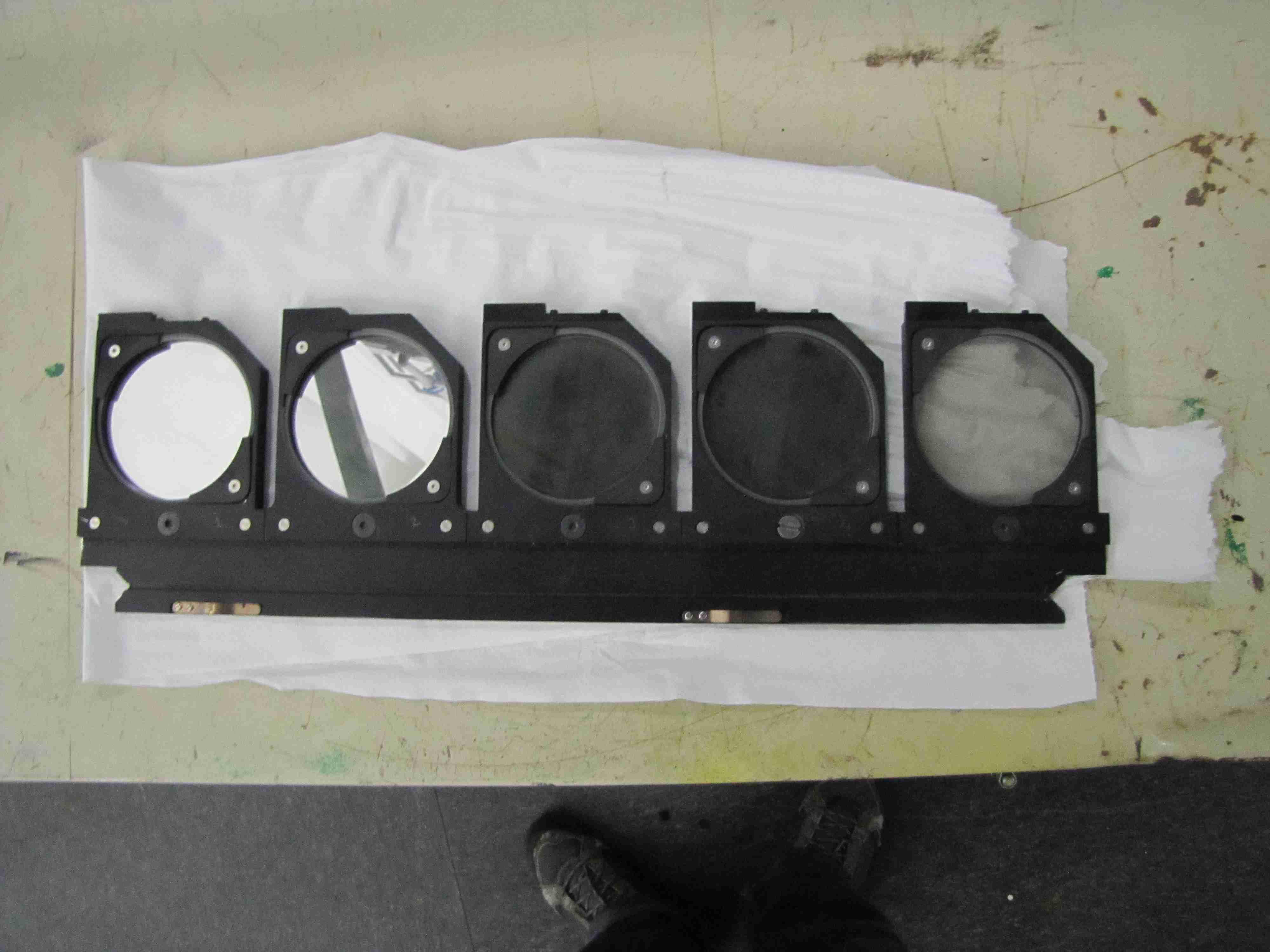
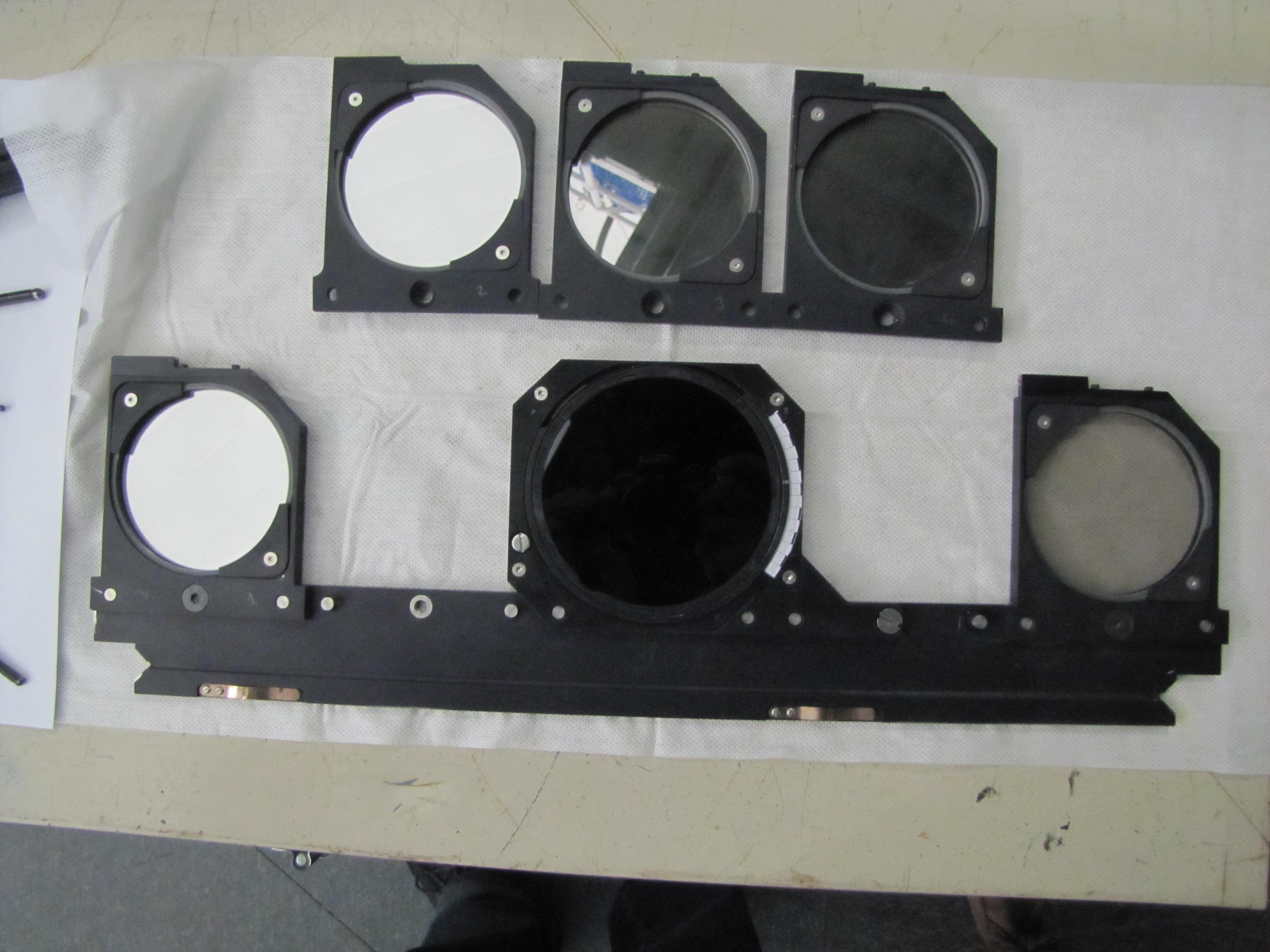
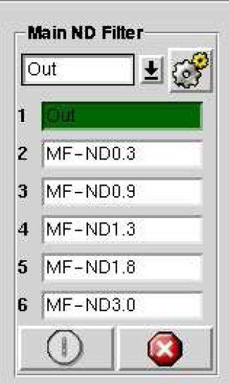
MOUNTING THE POLAROIDThe polaroid is mounted in the Main Neutral Density Filter Tray (Fig. 4-left, the top one).1. Go to the control Room and check that the Main ND Filter Tray is in 'Out' position. 2. Then go to the dome and open the auxiliary port door. Extract the Main ND Filter Tray. 3. Then remove the 2nd, 3rd and 4th ND filters. Use the 3rd position (middle) as indicated in Fig. 4 (right) to place the polaroid holder. 4. Put back the tray and update the main filter database. The position #4 of Main ND Filter window in A&G Box control should be modified, see Fig. 5 for the corresponding keyword. 5. There are different amount of screws needed when you mount the polaroid compared to the three ND filters. Do not lose the screws!
|

| Top | Back |
|
