IDS Gratings with the 235 mm Camera
General Characteristics
There two available CCDs detectors for IDS are
RED+2 (default detector) and
EEV10, the pixel size and scale
of the two detectors are:
RED+2 (default detector): 15.0 micron pixel with a scale of 66.7 pixels/mm and 0.44"/pixel, 2200 unvignetted pixels
EEV10: 13.5 micron pixel with a scale of 74.1 pixels/mm and 0.40"/pixel, 2275 unvignetted pixels (its use should be justified in the proposal).
IDS gratings have a ruled area of 102 mm x 128 mm. A wide selection of gratings is available, and some of the important characteristics of each grating are summarised in the Tables below. The last two columns in these tables list as a reference, the nominal spectral resolution for a 2 pixel slit projected at the detector. The resolutions were calculated for 4500 Å or 7000 Å according to the blaze angle of the gratings.Grating changes are done during day time by support staff. Programmes that may need more than one grating per run should request this in the proposal.
IDS gratings' characteristics and parameters for EEV10 |
Name1 |
Blaze (Å) |
Max. Eff.2 (%) |
Dispersion3 (Å mm-1) |
Dispersion
(Å pixel-1) |
Unvignetted range
(Å) |
Slit 27μm (2 pix) at detector4 (arcsec) |
Resolution at 4500 Å for 2 pix at detector |
Resolution at 7000 Å for 2 pix at detector |
R150V B |
5250 |
66 |
271.3 |
3.66 |
8327 |
0.93 |
615
--- |
R300VN |
5460 |
72 |
138.5 |
1.87 |
4254 |
0.95 | |
R400BB |
3900 |
50 |
104.5 |
1.41 |
3208 |
0.95 | |
R400VB |
5100 |
72 |
104.5 |
1.41 |
3208 |
0.97 | |
R400RB |
7250 |
59 |
104.4 |
1.41 |
3208 |
1.00 | |
R600RB |
6700 |
65 |
69.8 |
0.94 |
2139 |
1.04 | |
R600IRB |
10000 |
70 |
70.2 |
0.95 |
2139 |
1.07 | |
R632VN |
5460 |
72 |
66.5 |
0.90 |
2048 |
1.00 | |
R831RB |
7500 |
65 |
50.7 |
0.68 |
1547 |
1.14 | |
R900VB |
5100 |
69 |
46.4 |
0.63 |
1433 |
1.05 | |
R1200UJ,5 |
3500 |
68 |
35.3 |
0.48 |
1092 |
1.04 | |
R1200B J |
4000 |
76 |
35.3 |
0.48 |
1092 |
1.04 | |
R1200YB,6 |
6000 |
68 |
35.2 |
0.48 |
1092 |
1.20 | |
R1200RB |
8000 |
66 |
34.8 |
0.47 |
1069 |
1.23 | |
H1800VP |
5300 |
64 |
23.2 |
0.31 |
705 |
1.26 | |
H2400BJ |
4000 |
60 |
17.5 |
0.24 |
572 |
1.23 | | |
[1] Prefix R for 'ruled grating' and prefix H for 'holographic grating'. The number following the prefix is the grating ruling (number of lines per mm). The suffix following the grating ruling indicates the range in which the grating is more efficient. The superscript character at the end of the name denotes de origing of the grating by following code:
- B =Bausch and Lomb
- N =National Physical Laboratory
- J=Jobin-Yvon PTR/NPL
- P=PTR replica from NPL master
That is, a R150V grating is a ruled grating with low resolution, with 150 lines per mm, more efficient in the V-band (see that the blaze is at 5250 Å), made by Bausch and Lomb.
[2] Absolute efficiency values measured at RGO.
[3] At low and intermediate dispersions the dispersion changes little with the central wavelength.
[4] Along the dispersion direction, the slit to detector reduction factor depends on the grating angle. This column gives the width in arcsec which projects to 30 (27) microns at the detector, when each grating is used close to its blaze wavelength. Note that 30 (27) microns is 2 pixels in the detector, hence this is the minimum required slit width according to the sampling theorem (e.g. for proper sampling, the wavelength resolution can not be less than about two pixels). If a wider slit is used to increase the total throughput, the wavelength resolution will be degraded.
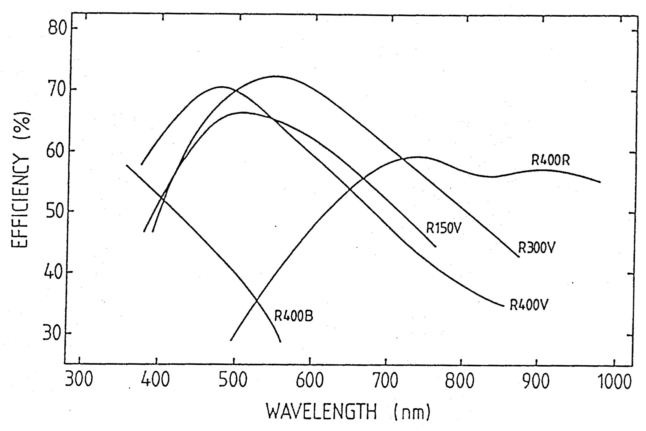
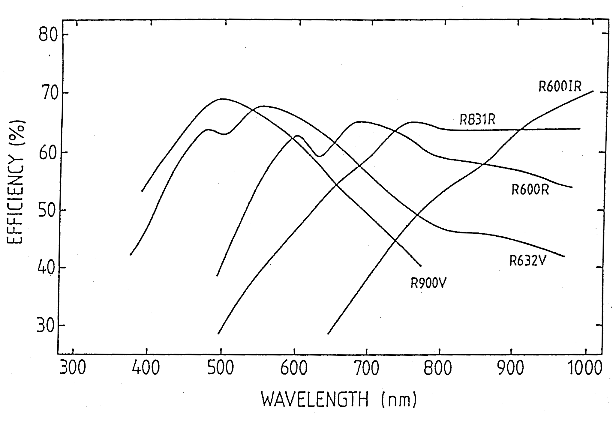
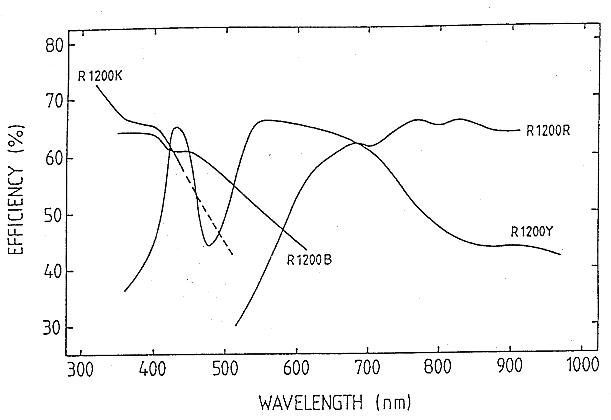
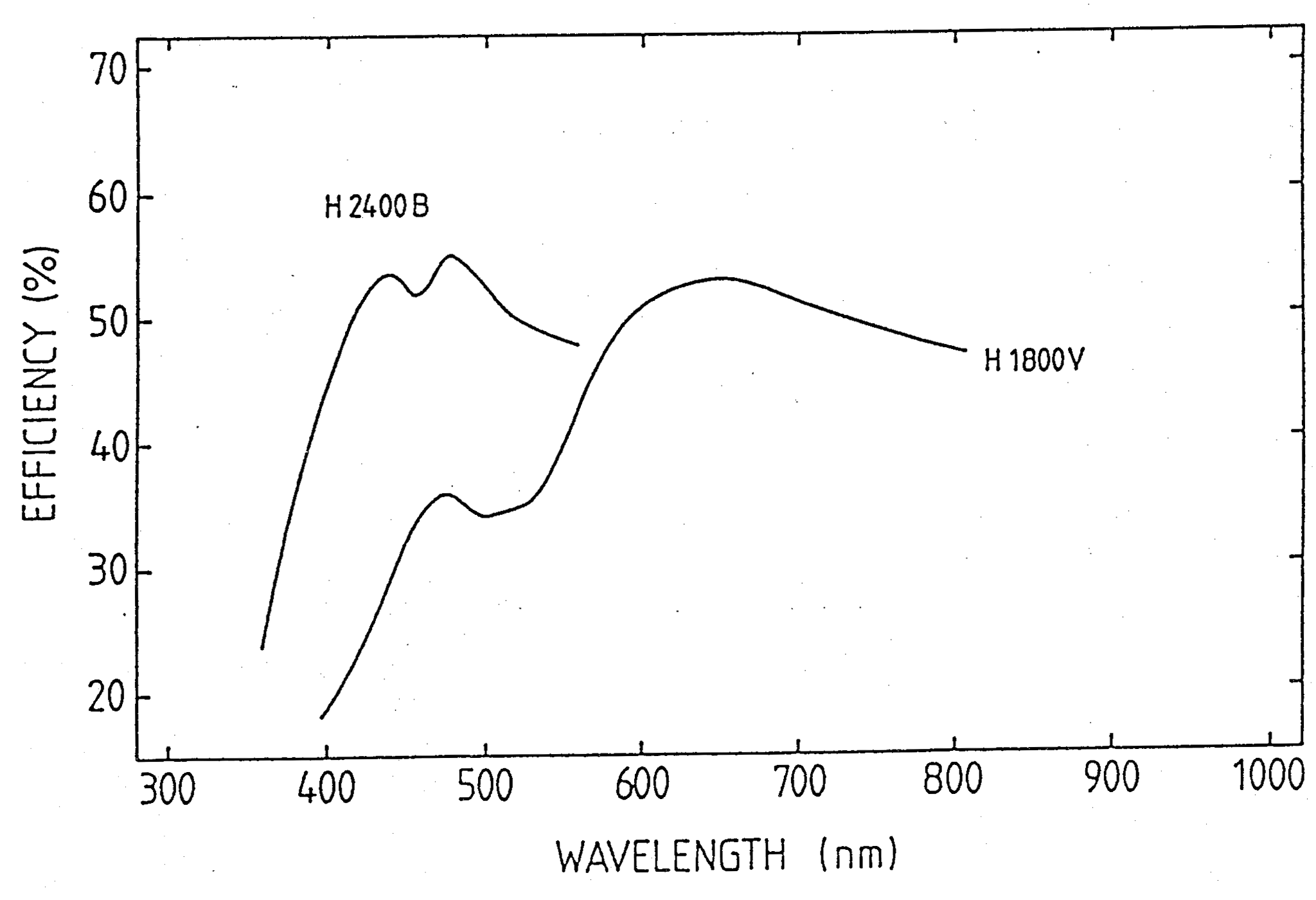
The efficiency of the gratings as a function of wavelength is shown in the Figures below.