| |||
|
Home > Public Information > ING Newsletter > No. 6, October 2002 > Telescopes and Instrumentation |
|
INGRID | SCIENCE |
|
|
|
Other available formats: PDF
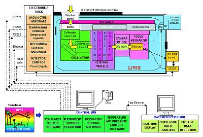
LIRIS: A Long-Slit Intermediate Resolution Infrared Spectrograph for the WHTFigure 1. LIRIS schematic representation. [ JPEG | TIFF ] |
From left to right: Figure 2. Collimator. Figure
3. Camera. Figure 4. Corning 9754 Gris. [ JPEG
| TIFF ] |
From left to right: Figure 5. Slit wheel. Figure
6. Pupil wheel. Figure 7. Camera wheel integrated in the test cryostat (dummy
on camera position). [ JPEG | TIFF ] |
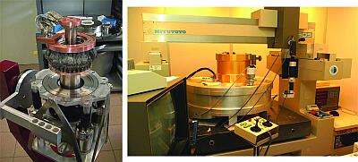
Left: Figure 8. Closed-cycle refrigerator with
the two-stage thermal links integrated. Right: Figure 9. Mechanism cryostat
on the Mitutoyo during the functional verification of the main central wheels
module. [ JPEG | TIFF
] |
From left to right: Figure 10. Main central wheel
module (filter wheel side) pre-integrated on LIRIS. Figure 11. Bottom view
of the slit wheel mechanism. Figure 12. Pre-integration of the slit wheel
on the LIRIS optical bench. [ JPEG | TIFF ] |
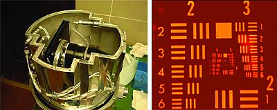
Left: Figure 13. Internal view of the detector
test cryostat. Right: Figure 14. Image of an USAFSR pattern taken with the
scientific grade detector, through the H-band filter. [ JPEG | TIFF ] |
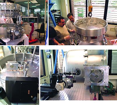
From top to bottom: Figures 15 and 16. Positioning
the optical bench on the trusses in the vacuum tank central ring (cables
provisionally fixed for this cycle). Figures 17 and 18. Optical bench with
the collimator and reticules placed in specific positions to check their
behaviour during the first cycle (these reticules were visible at all time
through a very useful cryostat auxiliary window, see Figure 18). A simulation
of the detector module was placed outside the beam line to test the detector
thermal control system. [ JPEG | TIFF ] |
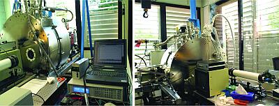
Left: Figure 19. LIRIS cryostat ready for the first
cycle. Right: Figure 20. Pre-cooling with liquid LN2. [ JPEG | TIFF ] |
Top | Back |
|