The hemispherical dome protects the telescope against the weather and the
input of undesirable heat during the day. The dome has a cavity structure
with insulation between the inner and outer skins; the dome walls, shutters
and windscreen are of aluminium. The dome is rotated by drive units mounted
on the building which can achieve a rotation in four minutes at top speed.
The azimuth of the dome is encoded and interfaced to the telescope control
computer. Because of the cross axis mount the azimuth of the dome is not in
general equal to the azimuth of the telescope but this divergence can be
handled by a simple algorithm. The dome is opened to a width of two metres
by two shutters moving horizontally. In addition there is a windscreen which
may be stowed horizontally or raised to a zenith distance of 15 degrees.
Mounted near the top of the dome is a one tonne hoist which may be used to
lift equipment from the basement through to the upper levels. This hoist is
also used to lower the primary mirror to the basement when it is taken to
the WHT for re-aluminising.
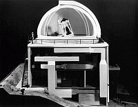 The building is a twelve metre square in plan and extends to three floors,
with the basement half-concealed by the steeply sloping hill. It is a
concrete structure surrounded by a reflecting screen to minimize radiation
heating during the day. There is a gap between the solar screens and the
outer building wall where air near ambient temperature is free to convect
away any transmitted heat.
The building is a twelve metre square in plan and extends to three floors,
with the basement half-concealed by the steeply sloping hill. It is a
concrete structure surrounded by a reflecting screen to minimize radiation
heating during the day. There is a gap between the solar screens and the
outer building wall where air near ambient temperature is free to convect
away any transmitted heat.
The basement contains the electrical intake room, the water tank and store
rooms. It has a bay with large double doors to bring equipment in and out.
The building is plumbed by a series of hatches so that equipment may be
conveniently lifted to the rising floor using the one tonne hoist on the
dome. The ground floor embraces the office, dark room, rest room and
instrument store. In addition there is a room containing the air
conditioning unit, the telescope control computer, the telescope drive
amplifiers and the time service. The upper floor contains the telescope
control room, a room used for the now retired 3220 computer and an instrument bay to hold
auxiliary instruments not in use. However the majority of this level is
taken up by the rising floor which carries observers and equipment to
convenient positions beneath the telescope. It is particularly useful when
setting up instruments, for exchanging the two top end rings and their
corresponding sky baffles, and when removing the primary mirror. It has a
load carrying capacity of two tonnes and a total travel of 2.3 metre from
the control room level. The rising floor was incorporated in the original
design because it was an important part of the Siding Spring 1-metre design,
from which the present telescope developed. In those days it was regarded as
essential by the observers and as a nuisance by the engineers. However in
the years needed to bring the project to fruition attitudes have changed.
The majority of instruments are now so highly automated that there is little
need for an observer to reach the eyepiece, even when one exists. While
observers no longer require the rising floor it is accepted as essential by
the engineering staff who can carry out many routine operations much more
easily with its help.


