 | |||
|

| Home > Astronomy > Detectors > QUCAM3 |
QUCAM3 Parameters with UltraDAS + SDSU Gen.3
Device Identification
| ||||||||||||||||||||||||||||||||||||||||||||||||||||||||||||||||||
| Chip name | QUCAM3 |
| Year of manufacture | 2008 |
| Serial number | 06453-06-06 |
| First light on La Palma | September 2008 |
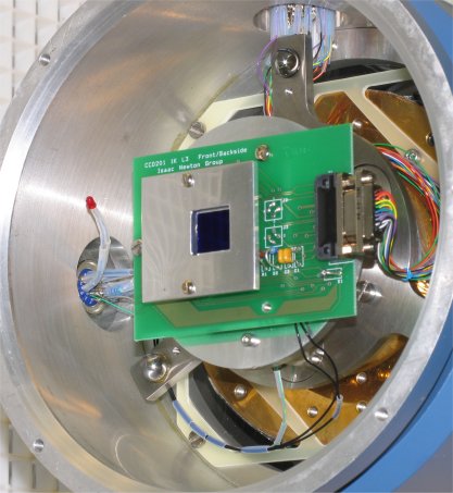
| Description | E2V CCD201-20-4-122 Thinned midband AR coated. L3 electron multiplying CCD. Camera Picture |
| A paper on 'The use of electron-multiplying
CCDs for astronomical spectroscopy' by S.Tulloch and V.Dhillon |
|
Operational Characteristics
| Speed | Fast | Slow |
| Bias (ADU) | 2400 | 1980 |
| Gain (ADU/e) | 0.0089 e/ADU 1e = 112 ADU | 1.04 e/ADU |
| Read Noise (e) | <1 | 4 |
| L3 Gain | 260 | 1 |
Recommended command for rapid spectroscopy is 'rmode spec'. This produces image sequences with very low timing jitter and supersedes the earlier 'rsrun' command.
'rmode spec' timings as follows:
| Window size | Fast | Slow |
| Full fame | 3.6s | 5.0s |
| window = 1080 x 512 | 1.8s | 3.0s |
| window = 1080 x 256 | 0.85s | 1.45s |
| window = 1080 x 128 | 0.45s | 0.75s |
1) The chip has been reoriented such that the spectra now lie with the spectral axis horizontal. This allows use of horizontal windows which permits faster readout.
2) Windows should include the full width of the chip or the L3 gain will be reduced from the figures quoted above.
3) Please note that when using the 'rmode spec' command the actual exposure time will be the sum of the readout times (in the table above) and the requested exposure time. This is because the CCD is operated in frame transfer mode and the exposure time is effectively the cycle time of the system when making image sequences.For information on the rmode spec syntax click here.
4) If exposure times of less than the frame readout time are required then it is necessary to use the' multrun' command. This is not recommended however since it will be very wasteful of photons. Multruns issue a clear to the CCD before every exposure and for an equal sized window are 0.3s slower to readout than a frame taken using 'rsrun'.
5) Engineering note: If the observer definitely requires multrun with very
short exposures (shorter than the mechanical shutter response time) it will
be necessary to hold open the shutter using the manual switch on the front panel
of the shutter rack and startup the observing system using a different version
of the software.
In this case the cameras are instead called QUCAM2NS (or QUCAM3NS) and this
name needs to appear in the configuration file.
6) 'whtdas14' or 'whtdas15' which have more RAM (2GB) than the other das
machines should be used with the Qucams. The Linux PCs
should not be used with either of the Qucams until further notice.
This camera has now been commissioned with the new Linx PCs.
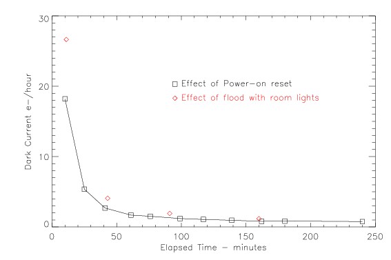
7) A reset of the controller including a dasreset should be avoided at all cost, it should certainly not be done during the DE checks, the result is increased dark current.
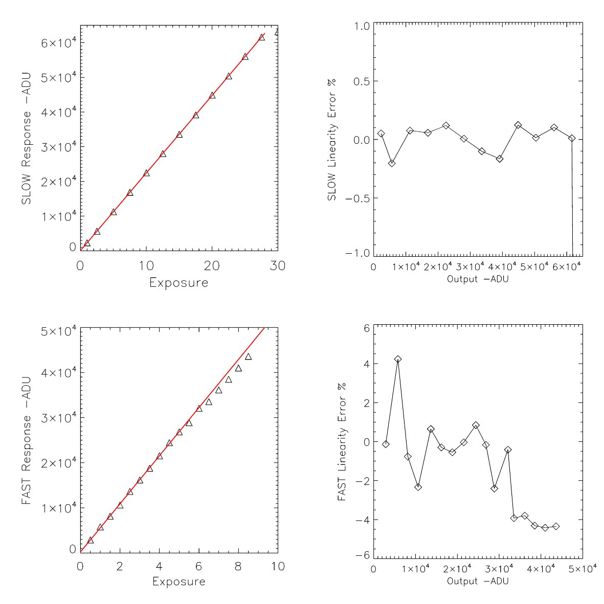
Linearity information here
Windowing : when used on ISIS the spectra will have the spectral axis
along a row. Windowing in x may produce a reduction in gain and should not be
used. Y windowing fully functional. The first 10-20 columns of an x-window will
contain a large gradient. The bias in Y is very flat although the first row
may contain some stray charge.
Binning : Only possible in Y
Physical Characteristics
| X Pixel size | 13 microns |
Y Pixel size |
13 microns |
| X size in pixels of digitised area | 1080 |
| Y size in pixels of digitised area | 1050 |
X size of useful imaging area |
1026 |
| Y size of useful imaging area | 1024 |
X start of useful imaging area |
24 |
Ystart of useful imaging area |
8 |
Operational Parameters
Operating temperature |
163K (requires 3 hour cool down to stabilise at operational temp, important for gain stability) |
Preferred Amplifier |
Both are used depending on the readout speed |
Measured Characteristics
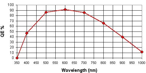
Predicted QE
| Clock induced charge | 0.010 e/pixel/readout |
5.3 e/pix per hour 1 hour after power on, falling to
|
Notes on use of camera
This L3 camera also has a conventional output. The user can select L3 operation by using 'rspeed fast' and conventional operation using 'rspeed slow'. Since these two amplifiers are positioned at different corners of the CCD they will produce mirrored images. i.e. if the user changes the readout speed they will observe the image to become horizontally flipped.
For information on which of the 2 outputs to use see this document.
Some papers describing the use of L3 CCDs see this link
Sample Images and Observing tips for L3 Cameras see this link
| Top | Back |
|
