 | |||
|

| Home > Astronomy > William Herschel Telescope > WHT Cassegrain Acquisition and Guider Unit |
|
| |||
|
| Home > Astronomy > William Herschel Telescope > WHT Cassegrain Acquisition and Guider Unit |
WHT Cassegrain Acquisition and Guider UnitThe WHT's Cassegrain acquisition and guider (A&G) unit provides acquisition, guiding and calibration facilities for instruments mounted at the Cassegrain and folded-Cassegrain foci. Sections below:
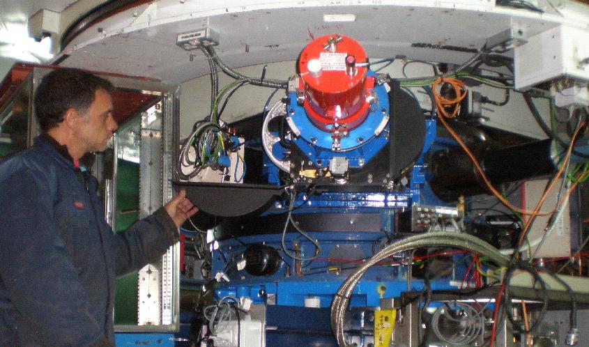
The Cassegrain A&G unit is the blue cylindrical section (diameter 1.50 m, height 0.65 m) mounted below the WHT's primary-mirror cell:
The top half of the A&G unit houses an acquisition camera, calibration (comparison) lamps (arc and continuum), a deployable 45-deg mirror feed for the ACAM imager/spectrograph (orange cryostat visible in above photo), and three additional deployable mirrors described below. The bottom half of the unit houses the A&G filter slides, and the Cassegrain autoguider. The A&G delivers a field of view of diameter 15 arcmin. The scale at the f/10.94 Cassegrain focal plane (150 mm below the lower surface of the A&G unit) is 4.51 arcsec/mm. The layout of the components in the upper half of the A&G unit is shown below. Light from the telescope enters along the axis of the cylinder and either exits through the hole in the base to the bottom half (not present here) and downstream instrumentation, or is intercepted by one of the 45-deg mirrors that can be deployed into the optical path. Clockwise from the bottom of the photo, the components visible in the A&G (mirrors are all in their parked positions) are: elliptical feed mirror for ACAM; slit-view mirror (bottom left, allows the ISIS slit to be viewed by the acquisition camera); optics barrels (top left) of acquisition camera; mirror (top) to reflect light from calibration lamps to ACAM; the acq/comp mirror (top right); ACAM (right); and the exit lens of the calibration-lamp unit. The two-sided acq/comp mirror has two functions: it reflects calibration light downwards (e.g. to the ISIS slit) and simultaneously reflects light from the sky to the acquisition camera. The ACAM science mirror is mounted on a carriage; the other three mirrors are mounted on probes. The photo (click for an enlargement) was taken in 2013 by Neil O'Mahony. 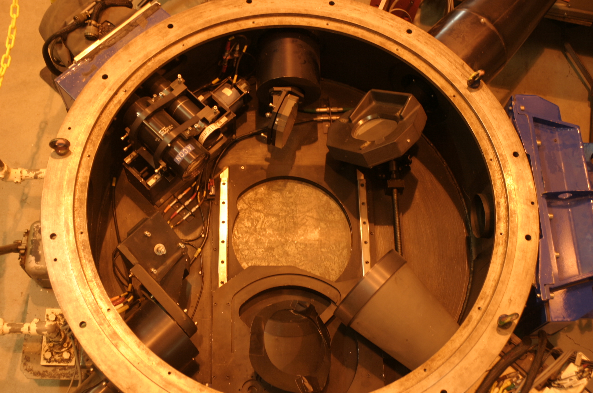
The (older) diagram below (A&G rotated ~ 90 deg clockwise relative to the photo above) provides some labelling. A couple of things have changed since the figure was produced: the carriage supporting the 'fibre-optic feed mirror' now supports the 45-deg flat feeding ACAM; and the 'small feed flat' probe now carries the mirror for directing light from the calibration lamps to ACAM. 
Commands for controlling the various A&G-unit mechanisms can be found in the WHT command glossary. Movement in or out of one of the A&G mirrors typically takes only 5 - 10 sec. E.g. when observing with ISIS, switching between science-observing/slit-viewing mode, to internal calibration mode (light fed from calibration lamps to ISIS slit) takes about 15 sec. Similarly, when observing with ACAM, switching from science to calibration mirrors takes ~ 17 sec. The optics in the A&G box (as in any Cassegrain instrument, e.g. ISIS) are susceptible to contamination from dust ('calima'), and require regular monitoring and occasional cleaning. The A&G box includes several sets of filters, which are listed in ING's internal ING filters database: #996-1009 in the A&G filter slides; #1026-1030 for the autoguider; and #1010-1025 for the calibration lamps. Filters #1031-1035 were formerly for use with the acquisition camera but the filter wheel is no longer present. Teams planning to mount new visitor instruments at WHT Cassegrain should consult the visitor-instruments page. The acquisition camera can be used to view the reflective back of the ISIS slit, which is tilted at an angle of 7.4 deg to allow this. The full 4 arcmin of the slit can be seen (when using the standard focal reducer in front of the camera):
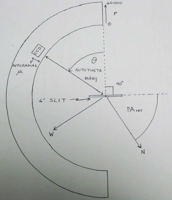
There are no filters in the camera. Stars of apparent mag < 19 can be detected in an integration time of a few sec, in dark of moon. (The throughput of reflective slit + camera optics is ~ 0.1, corresponding to ~ 300 counts per sec for V = 20.) The camera can also be used to view the sky directly, rather than via reflection off the ISIS slit. The unvignetted field of view is approx 4.5 arcmin along the slit (x direction as usually viewed) x 2.9 arcmin perpendicular to the slit. The scale is ~ 0.23 arcsec/pixel. The image is usually viewed with the x direction flipped, so that it has the same parity as sky (this also means that the directions on the TCS handset buttons make sense). After this flip, at sky PA = 0, north is right, east is up (as viewed on the display screen). At sky PA = 90, north is down, east is right. The star images delivered by the Cass acquisition camera are imperfect, with a faint tail to the lower right (when displayed x-flipped, as above), PA ~ 340 (as measured from 'right' through 'up'). The tail contains ~ 15% of the total light, and can be modelled very roughly as a gaussian with FWHM ~ 4 arcsec, and centred ~ 2.5 arcsec from the main star image. The PSF varies across the field of view, e.g. at bottom right the PA of the tail is ~ 320. The PSF does not vary with telescope pointing. A focal reducer can be inserted before the acquisition camera to decrease the scale (i.e. fewer arcsec/mm) by a factor of 2.5, but it is rarely used. The TV can be refocused (+- 1 cm) as required. The slit-view optics are partially vignetted by the autoguider head if the latter is positioned at angle theta < 35000. The detector in the acquisition camera is the AG4 CCD, 13-micron pixels, peak QE ~ 0.9 (FWHM of QE curve = 4000 - 8800 A). The autoguider detector has a field of view of ~ 1 arcmin, and the head (right-angled pickoff prism, focal-reducing lens, filter wheel and detector) can be driven anywhere within a half annulus (0 to 177 deg) of radius 8.2 to 11.2 arcmin, (110 to 150 mm) i.e. total area available = 0.04 deg2. This gives a good chance of finding a guide star brighter than 11th mag at the galactic equator, or 13th mag at the galactic pole. In practice, mag = 11 stars may saturate the CCD in clear conditions, so the telescope operators typically select (from the guide-star server, AutoGSS) stars with mag ~ 13.5, and use the 'clear' filter. If the I filter is used (e.g. when observing with LIRIS), brighter guide stars are probably needed. The autoguider coordinates used by the observing system are r and theta. r is radius (minus 110 mm) in microns (i.e. ranges 0 - 40000), and theta is in millideg (i.e. ranges 0 - 177000).The scale is 0.23 arcsec/pixel on the autoguider CCD. The graphic below (by Michiel van der Hoeven) shows the layout of the mechanisms in the autoguider:
The sketch below indicates the relative size of the ISIS slit and the semi-annular area within which the autoguider can be positioned:
The autoguider is equipped with a 6-position filter wheel: clear (UBK7), B (BG28), V (BG38), I (RG630), opaque and empty. The B, V, I and clear filters all have the same thickness. The diameter of the filters is 23 mm. The autoguider includes an internal focus mechanism (+- 4 mm) to allow for different filter thicknesses. A 1-mm change in telescope focus can be compensated by a change in autoguider focus of 4200 (microns, i.e. 4.2 mm). The autoguider probe is not usually used at theta < 35 deg, where it significantly affects the slit-viewing optics. The detector is CCD AG6, 560 x 536 13-micron pixels, peak QE ~ 0.94 (FWHM of QE curve = 4500 - 8500 A). The calibration-lamp system comprises an integrating sphere into which is fed light from two hollow-cathode lamps (CuAr and CuNe for arc spectra) and light from a tungsten (W) continuum lamp. When LIRIS is mounted, the CuAr lamp is replaced by a xenon lamp, so if ACAM is used during a LIRIS run, only CuAr is available for the ACAM arc spectra.The integrating sphere for the calibration lamps can be seen to the left of the diagram in Section 1 above. The exit pupil of the integrating sphere is fitted with an obscuring disk to simulate the obscuration of the telescope pupil by the secondary-mirror structure. Two 8-position filter wheels are provided. These are used mainly to insert 75-mm-diameter ND filters to avoid saturation of calibration exposures, particularly when using the tungsten continuum lamp. These filters are not strictly neutral, with relative throughput between 5500 and 8500 A varying by several 10s of %. The reverse side of the acquisition mirror (see section 1 above) is used to feed calibration light to the instrument, so that in principle calibration exposures can be taken at the same time as target acquisition. The W lamp is mounted vertically below the integrating sphere. If the W lamp is on, and the WHT dome lights are off, white light should easily be visible leaking from this position (useful test in case you are wondering if the bulb has failed). The A&G unit includes two five-filter slides, nominally for colour and neutral-density (ND) filters respectively. Each filter is mounted in a cell, and the cells for the two slides are identical. The filters are mainly of diameter 80 - 85 mm.The 'colour' slide usually contains polarisation filters and wave plates used when setting up ISIS or LIRIS for a polarisation run. After an instrument change from ISIS to LIRIS, the optical polarisation filters and wave plates are swapped for near-IR ones (and the reverse when there is a change from LIRIS to ISIS). The other filters in this slide (e.g. GG395, RG695) are little used. The access hatch for the filter slides is close to the bottom edge of the A&G unit. Azimuthally, it's near the top of the photo in Section 3 above, and the slides lie beneath the autoguider mechanisms. Illustrations of the filter slides and the access hatch, and instructions for effecting filter changes, can be found on the LIRIS setup page. The ND filters (usually ND = 0.3, 0.9, 1.3, 1.8 and 3.0) are occasionally used when acquiring unusually bright targets onto the ISIS slit. It's not known how flat (grey) the response of these filters is. There are 2 folded-Cassegrain ports (side ports), at one of which is mounted the imager/spectrograph ACAM. The other port is not currently used. The INGRID near-IR camera was originally mounted at one of these ports. Additional technical information about the A&G can be found in La Palma techical note 56 (published 1988), and in Ellis et al 1990 (SPIE 1235, 777).Side view of the A&G unit (from the 1994 ING Observers' Guide): 
More information about the autoguider can be found in a 2008 presentation (only visible at ING) by Michiel van der Hoeven. |
| Top | Back |
|
