 | |||
|

| Home > Astronomy > NAOMI > Description |
|
| |||
|
| Home > Astronomy > NAOMI > Description |
NAOMI DescriptionNAOMI, the WHT's adaptive-optics (AO) system, is mounted on an optical bench at the Nasmyth focus. The key components are the 10*10 Shack-Hartmann wavefront sensor (WFS), the 76-element Thermotrex segmented deformable mirror (DM), and the Zeiss tip-tilt mirror. The wavefront sensor measures the distortion of the incoming wavefront, and the deformable mirror is configured (many times per second) to cancel these distortions, yielding a near-diffraction-limited image at the science camera (currently INGRID).The DMs of most AO systems have continuous face-sheets. NAOMI is unusual in having a segmented DM. Segmented mirrors allow better correction at short wavelengths, but have higher IR emissivity (from the gaps between the segments), and the afternoon setup (mirror-flattening) is complicated. Positioning of the individual segments of the NAOMI DM is particularly accurate, thanks to the unique strain-gauge feedback which ensures a linear response to the requested wavefront corrections. NAOMI is also unusual in having a moveable pickoff mirror to direct light from a guide star anywhere in the field, to the WFS, allowing the science object to be on-axis, which is an advantage for IR observing. NAOMI was designed to deliver, under median-seeing conditions, Strehl > 0.25 over 25% of the sky, in K band (2.2 microns), and Strehl > 0.7 over 5% of the sky. At shorter wavelengths, the performance will not be diffraction limited, but there will be partial correction. NAOMI is not expected to provide good correction in seeing worse than 1.2 arcsec (when there are large phase changes across individual mirror segments). NAOMI will operate with natural guide stars, but has been designed for simple upgrade to operation with single laser guide stars. More information about the NAOMI project, including science requirements, and top-level and technical descriptions, can be found on the Durham and ATC NAOMI pages and in the Myers et al (2002) SPIE paper (pdf format).
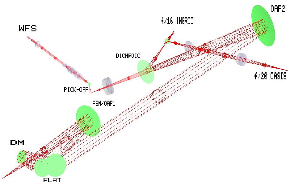
The components of the AO system between the
sky and the wavefront sensor are:
the telescope (primary, secondary and Nasmyth mirrors),
the
Nasmyth derotator,
calibration unit,
(pinhole),
fast-steering mirror = OAP1,
fold flat,
deformable mirror,
fold flat again,
off-axis paraboloid 2,
dichroic,
(WFS layout),
WFS pickoff mirror,
WFS filter,
WFS atmospheric-dispersion compensator,
WFS collimator,
WFS lenslet wheel,
WFS CCD.
Click on one of the links above to be directed to relevant notes below. The derotator is a K-reflector, with 3 overcoated-silver surfaces. In addition there is a window at either end, i.e. 7 surfaces in all. The windows were installed to prevent air flow through the derotator, but may have significant emissivity in K band. Transmission of the derotator is about 0.75 (7/2000), some of the light possibly being lost due to polarisation effects (light reflected at an angle to the normal). The derotator radiates about 10 W. NAOMI is currently (8/2002) housed in a light-tight enclosure, GHRIL, on one Nasmyth platform. In winter 2002, it will move to a new purpose-built enclosure, GRACE, on the opposite Nasmyth platform, formerly occupied by UES. NAOMI radiates about 200 W into the enclosure.
Starlight enters NAOMI from the telescope 150 mm above the optical bench. At night the bench rests on its kinematic supports. During afternoon setup the bench is floated to minimise vibrations (to which the fisba interferometer is very sensitive). The new calibration unit (built prior to installation of OASIS 2003?) can be driven horizontally across the beam to any one of 5 positions: simplex pinhole, 'OSCA pre-stop' (in practice, never commissioned), continuum lamp (for OASIS flats, micro-pupils), acqusition/arc and science (NCU out of light path). The apertures at each of the first four positions are threaded to accommodate interchangeable pinholes (2-, 5-, 50-, 100-micron etc.) and opal diffusers. The 2-micron pinhole is usually mounted at the simplex position. In the acquisition/arc position, the f/11 beam from the sky is reflected upwards into the tube of the acquisition camera where it encounters a field lens (in the focal plane), then an imaging lens (~ 200 mm higher up), then the AG3 CCD (1k * 1k, 0.4 arcsec/pixel, 200-arcsec circular field of view). Dust on the field lens will be in focus on the CCD images.
(The old calibration unit included a beamsplitter. With the beamsplitter
deployed, most of the incoming starlight was fed to a TV camera
(field of view ~ 20 arcsec at 8/2002).
When it was withdrawn, the brightness of the star images on the WFS
increased by considerably more than a factor of two.
The beamsplitter also directed light from the calibration lamp into
NAOMI.
The pinhole is placed on a kinematic mount at the Nasmyth focal plane, just in front of the calibration unit. The 10-micron pinhole is usually used, others are available. MFB 24/2/03 reports that the standard 10-mic pinhole is not circular, and substrate is thicker than new pinholes (which would reduce throughput). The Zeiss (Jena) fast-steering mirror is an off-axis paraboloid, and has two functions. It collimates the beam, and it provides fast tip-tilt correction, up to 5 arcsec, at up to 20 Hz. It has about twice the throw of the ELECTRA FSM (its predecessor, which is the backup), and higher bandwidth, ~ 200 Hz at zero amplitude, 10 Hz at end of range. It now has an LED display to show when it is in-range?? Cross-hairs can be installed across it. The fold flat directs the collimated beam from the fast-steering mirror, to the DM, and then directs the beam reflected from the DM to the second off-axis paraboloid. It serves mainly to fold the light beam, to prevent crowding on the bench, but also permits the fisba interferometer a clear view of the DM. The flat is now clamped to the bench. The The 76-element linearised segmented deformable mirror was manufactured by Trex Enterprises in California. It's the only Thermotrex mirror in use for non-military purposes. Most AO systems use continuous-face-sheet Xinetics mirrors. For more information about the HV amplifiers, see here. The 76 mirror segments are laid out on a 10*10 square grid with the corners missing (photo from Myers et al):
The central 4 segments are not used, because they are obstructed by the WHT secondary-mirror. Each mirror segment has 3 actuators, which between them provide tip, tilt and piston movements. The mirror thus has 72*3 = 216 degrees of freedom. The 24 peripheral segments lie mainly outside the telescope pupil, so most of the AO correction is made using only 48 segments. The diameter of an individual segment is 7.6 mm. The WHT pupil has a diameter on the DM of 7.3 segments (the extra ones are for a possible future upgrade allowing conjugation to individual turbulent layers in the atmosphere, which would move the pupil image on the DM). The segments are aluminised and ??, they should never need recoating. 2% of the starlight is lost to the gaps between the segments. Each actuator has total range 6 microns?, read out as DACs 0 - 8192, 1 DAC unit = 15 A according to RM. There is a mask available for the 4 central elements, it screws into the same holes as the mirror cover. The DM loop runs at up to 300 Hz, the strain gauges at up to 3000 Hz (there's always a factor of at least 10 between these numbers, to avoid oscillations). The strain-gauge feedback is unique to NAOMI. It reduces hysteresis (otherwise 15%) when positioning the mirror segments, so that they can be positioned in one shot (precision ~ 120 A?), allowing for quicker response. Several are in 'pass-thru' mode, with the strain-gauge correction inacive, because the laser flattening is very sensitive to jitter on these segments ('sin bin' runs these channels). The strain-gauge loop currently operates at 3.3 kHz, with a goal of eventually running at 10 kHz. The strain gauges are sensitive to electronic noise because the circuits are not grounded. Some are particularly sensitive, e.g. that for mirror segment 63 channel C affects the signal for channel B, so this mirror segment and ~ 10 others (at 8/02) are on 'pass-thru'; the strain gauges are ignored.
A few garbled notes on SG:
In the event of failure, ELECTRA's Xinetics mirror is the backup. Xinetics mirrors are electrostatic (not piezoelectric) and have very small hysteresis, but only at one temperature. The second off-axis paraboloid (the first is the fast-steering mirror) is designed to deliver an f/16.5 beam, scale 350 microns/arcsec in the focal planes near the WFS pickoff mirror and between the dichroic and INGRID. Actually delivers f/16.1 because of manufacturing error (AJL email 25/4/03). Short wavelengths pass through the dichroic to the WFS (and any other camera, e.g. SLODAR, behind the glass plate supporting the pickoff mirror). Long wavelengths are reflected to the science camera. An automatic dichroic changer will be implemented for use with OASIS, to position dichroics within 10-microns, for 20-mic focus shift at OASIS. Simplex probably needed for each dichroic, mainly because of wavelength-dependent effects in optics downstream of dichroic, rather than because of dichroics themselves. The Barr IR dichroic cost 20000 UK pounds. Light impinged on the old (pre-OASIS) dichroic at 23 deg to the normal. One simplex should suffice for all dichroics, because the dichroic is near focus, surface imperfections don't matter too much. The dichroic changer positions the dichroics with an angular tolerance of 7 arcmin.
3D CAD model of the WFS, from Myers et al (2002) , showing the pickoff stage, foreoptics (ADC, filter, lenslet) and camera stage. The three stages move independently on the track. The pickoff mirror has a diameter of 5 arcsec, and sits on a small strut mounted perpendicular to a vertical glass plate at one end of the WFS unit. The glass plate moves the pickoff mirror horizontally (x) and vertically (y) in the field, to intercept light from the guide star (unvignetted field 2 arcmin), and direct it to the WFS. As the pickoff mirror moves in x and y, the WFS foreoptics move along the track to compensate for the change in focus. The spots on the WFS begin to disappear when the telescope is moved 4 arcsec from nominal position (so maybe the diameter of the pickoff mirror is > 5 arcsec?). The pickoff mirror lies close to a focal plane, but a few mm away, to minimise the effect of any dust particles on its surface. The field of view is limited by the derotator(?). For stars up to 60 arcsec off-axis, there is no vignetting of the spot pattern on the WFS. At 70 arcsec, there is ~ 10% vignetting. At 80 arcsec, there is severe vignetting. (Checked by CRB 9/04). Until ~ 3/2002, there was no stop in the focal plane near the pickoff mirror, which meant, unusually for an AO system, that the sky was not being properly baffled i.e. each WFS cell sees overlapping skies. E.g. if the pickoff feeds a 5-arcsec field, each 2-arcsec cell sees ~ 2.5 * 2.5 x true sky brightness. Tom Gregory noted this ~ 6/2001 and designed a stop which fits on the stem supporting the pickoff mirror. It is effective in reducing background light by the appropriate factor, and on-sky 5/2002 it did indeed appear easier to acquire faint stars. Objects subtending > 2 arcsec (e.g. Neptune) cannot currently be acquired on the WFS. The pickoff mirror is preceded by a lens which makes the beam passing through the dichroic telecentric, to minimise the curvature of the focal plane near the pickoff mirror (the WFS compensates in focus for the residual curvature?). The pickoff mirror is followed by another 45-deg feed mirror, above it, which directs the light horizontally into the WFS chassis. The combination of pickoff and feed mirrors may be acting as crossed polaroids if they are AR-coated with a dielectric, thus reducing throughput. Tom Gregory plans to replace them. Light from the remainder of the field (i.e. except for a region of diameter 5 arcsec) passes through the glass plate and can be intercepted by a camera behind the WFS (e.g. JOSE, SLODAR, LGS WFS). Cleaning: use a swab.
In most AO systems (including
ELECTRA,
NAOMI's predecessor),
light from the guide star is on-axis.
The ADC corrects for atmospheric dispersion, for zenith angles up to 60 deg. It comprises two counter-rotating prisms. The angle to which the prisms must rotate is based on the zenith distance supplied by the telescope control system. At 8/2002, the ADC has not yet been commissioned. The WFS collimator has focal length 136.54 mm. The contents of the lenslet wheel at 8/2002 are:
The grid of spots from the lenslet array is imaged onto a back-illuminated, Peltier-cooled, 80x80 EEV CCD39-01 (24-micron pixels). For the good-seing lenslet, each spot is imaged in a cell of 8*8 pixels, which can be read out in a variety of ways e.g. as 8*8 pixels, or the central 4*4 pixels binned as 2*2 pixels read out (quad-cell mode). Read noise in fast mode (usual) is 4.5 e- (in slow mode about 3.5 e-), gain 0.56 e-/count. (SMT measured 9 ADU in fast mode 4/05; and 5.2 e- 14/3/06 ). Dark current (estimate from SMT 5/05) is 20e-/pixel/sec for the master CCD, 13 for the slave, probably with the cold side of the chiller at -40 degC. The CCD is usually run in fast mode. Slow is too slow for AO, except maybe for integrations longer than 25 msec. QE = 0.8 over range 4000 - 7000 A. Maximum speed so far (9/2000) is 300 Hz. Readout overhead in 8*8 unbinned mode is 8.5 msec. The 4 quadrants of the CCD are read out separately, and each is processed independently within the C40 ring. Flat-fields are not required by the processing algorithm. There were originally 2 CCDs (master and slave), with a deployable 50/50 dichroic sending a similar image to each. The x centroids could then be measured by binning one CCD, and the y centroids by binning the CCD in the other direction, allowing the AO loop to be run faster. This was never commissioned, and the slave CCD has now (late 2005) been replaced by the L3 CCD. The dichroic has been replaced by a deployable flat. The manual switch (slide) on the front of the camera has 4 positions: out, CCD39, L3, out. The L3 CCD has a read noise of 0.74 e- (SMT 14/3/06). The CCD is preceded by 3 optical components, a telecentrising lens, the CCD window, and the dichroic. The wavefront sensor was built at RAL. It is not that same as that used in ELECTRA (NAOMI's predecessor), e.g. it is achromatic. Possible upgrade: zero-noise CCD (NB micro-channel plates are unattractive because of low QE). WFS overheads measured by IKS 10/03: g1 19.8 and 6.2 msec in slow and fast modes, g11 6.1 and 2.4 msec in slow and fast modes. Readout noise is 4.2 and 7 e- in slow and fast modes. Gain in slow mode is 0.6 e-/count. The Fisba is a Twynam-Green phase-shifting double-pass He-Ne 632.8-nm interferometer. It views the DM via the FISBA flat, and via the NAOMI fold flat. The laser itself hangs above the GHRIL bench, feeding the optics via a fibre. The laser is left on during observing. It provides a real-time indication of what the mirror segments are doing (although this is often masked by vibrations, when the optical bench rests on its kinematic mounts).
Acronyms
ELECTRA stands for ELEment Cophasing and TRAcking. MARTINI stands for something. |
| Top | Back |
|
