WEAVE parameters
This is a ready-reference summary of
WEAVE parameters.
It's updated at intervals for consistency with
the formal WEAVE documentation on the bscw and on the confluence pages.
For the most recent information,
people working on WEAVE should consult the bscw and confluence documentation.
Unless otherwise stated, the numerical parameters are design or
specification values. Many of these will be updated with measured values during (and after) commissioning.
Version 0.93, 14/11/25
Sections below:
- KEY PARAMETERS
- Telescope
- New top-end structure
- Prime-focus corrector, focal plane
- Focal-plane imager (FPI)
-
Fibre positioning, tumbler
-
MOS, mIFUs, acquisition, autoguiding, dithering
- LIFU + autoguider
- Calibration unit
- Spectrograph
- Detectors
- Spectroscopic performance
- Throughput
- Environmental constraints, and impact on environment
- Data flow
- Surveys
- Observing conditions
- Appendix 1 - Abbreviations
Within each section, links (click on the icons) are provided
to relevant (though not necessarily
up-to-date) images/graphics, mainly
from the WEAVE documents on the bscw. For captions, and further
explanation, see the original documents.
[ ] indicates source of information, ideally a WEAVE document, but
sometimes the initials of a person providing an update
[IDS-nnn] = information from requirement number
nnn in the Instrument Development Specification (= WEAVE-SYS-001)
This section reproduces key information
from sections 2 - 10 below. For more detail, refer to the relevant sections.
Field of view, image quality
Field of view: 2 deg diameter
Image quality: 80% encircled energy diameter < 1.0 arcsec
MOS mode
Multiplex: 960 fibres on plate A, 940 on plate B
Minimum fibre separation on the sky: 60 arcsec
On-sky aperture: 1.3 arcsec
Positional accuracy: <~ 0.2 arcsec rms
Time to position 960 fibres: 1 hour
mini-IFUs (mIFUs) mode
Number of mIFUs: 20
Minimum separation of mIFUs on the sky: 60 arcsec
Field of view of each mIFU: 11x12 arcsec2
Structure of each mIFU: 37 close-packed 1.3-arcsec fibres
(of the same type as used for MOS-A, MOS-B)
Large IFU (LIFU) mode
Field of view: 78 x 90 arcsec2
Fibre diameter: 2.6 arcsec
Spectroscopic performance (MOS, mIFU modes)
Low-res mode: R = 5000, blue arm 366 - 606 nm, red arm 579 - 959 nm
High-res mode: R = 20000, blue arm 404 - 465 nm or 473 - 545 nm, red arm 595 - 685 nm
Spacing in y of spectra on the detector: 6 pixels
Spectroscopic performance (LIFU mode)
In LIFU mode, the wavelength ranges are the same as quoted for MOS/mIFU
above, but the spectroscopic resolutions R are lower by a factor of two (due to the fibres having twice the diameter of the MOS fibres), R = 2500 and 10000 in
low-res and high-res modes respectively.
Spacing in y of the spectra (within a given slitlet) on the detector: 9 pixels
Detectors
Format: two 6k * 6k CCDs in each arm, with only 6k*8k of
each CCD-pair used for science
Pixel size: 15 micron
Readout time: 60 sec (4 CCDs read out simultaneously)
Autoguiding
Number of guide fibres: 8 (on each plate)
Mag of guide stars: < 15
Overall throughput of WHT+WEAVE
Low-res mode, 450 - 850 nm: 0.25 - 0.33, depending on wavelength
High-res mode: 0.10 - 0.25, depending on wavelength


(images from WEAVE-PRI-011 and ? respectively)
The following information about the WHT
is taken from the
ING Observers Guide and
the
WHT quality-control pages.
Mechanical
Azimuth limits: -175 -> 355 deg
Elevation limits: 10 deg (vignetting below 12 deg) -> 89.8 deg
(zenith blind spot)
Slew speeds: maximum 1 deg/sec in both azimuth and elevation
Pointing accuracy: 1 - 2 arcsec rms at prime focus
Open-loop tracking: typically accurate to 1 arcsec over 10 min
Closed-loop tracking: < 0.2 arcsec rms
Mass of telescope: 190 t
Primary mirror
Size, shape : 4.2 m diameter, 0.5 m thick, paraboloid,
focal length 10.4 m (f/2.5)
Reflectivity:
typically 0.82 - 0.89, depending on when last aluminised
Image quality at prime focus: < 0.3 arcsec FWHM


(from WEAVE-PRI-002, WEAVE-POS-009 and WEAVE-POS-002 respectively)
The new top-end structure
comprises five new components: the corrector/ADC optics, rotator and fibre positioner/plates, and the supporting
vanes and focus-translation system (FTS).
The new top end will require new handling and storage
equipment (graphics on separate page).
The information below is taken from Dalton et al (2014, SPIE).
Focus translation
 (from WEAVE-PRI-022)
Range: +- 3 mm
Accuracy 5 micron
Field rotator
 (from WEAVE-PRI-018)
Angular range: -155 < mount PA < 155 deg
Direction convention: as viewed from M1, an anti-clockwise rotation
of the rotator corresponds to an increase in mount PA
Slew speed: ~ 1 deg/sec
Tracking accuracy: 0.05 arcsec/hour
Mass
Total mass at top end: 4 t (including new top-end ring, prime-focus
corrector and fibre positioner)
Instrument change from Cassegrain to WEAVE, or vice versa
 (removal of current flip ring,
from WEAVE-PRI-011)
(removal of current flip ring,
from WEAVE-PRI-011)
Duration: several days (i.e. several nights without observing)
[ING operations team]
The information below is taken from Agocs et al (2014 SPIE)
or from Dalton et al (2014 SPIE) unless
otherwise stated.
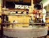
Prime-focus corrector optics
Optics, 6 lenses L1 - L6:
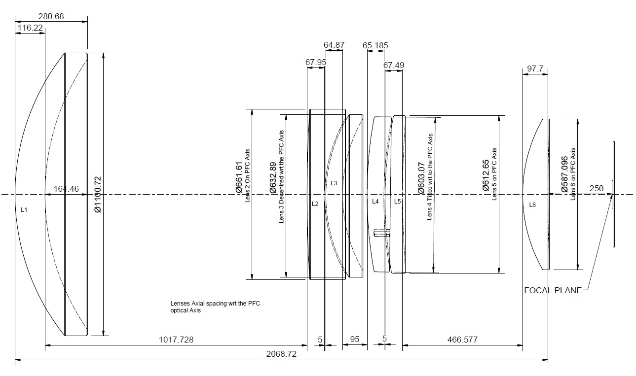
The figure above shows the PFC as-built (from WEAVE-PRI-014.7). Click on figure to see full-size.
 (cross-section, from WEAVE-PRI-018)
ADC = L2 - L5 (pair of counter-rotating prisms):
 (from WEAVE-PRI-018)
 (from WEAVE-PRI-011)
Lens diameters: largest is L1, diameter 1100 mm
 (details for L1 - 6, from WEAVE-PRI-011)
Lens materials: silica, S-BSL7, PBL1Y, PBL1Y, N-BK7, silica [EL 12/2016]
Lens anti-reflection coatings: ~ 1% for L2-6; L1 is not coated
(to minimise risk of fracture)
Lens holders:
 (from WEAVE-PRI-011)
Field of view
Field of view: 2 deg diameter
Radius-dependent vignetting: < 3% at edge of field of view
(design performance) [WEAVE-PRI-028.02]
Image quality
Image quality: 80% encircled energy diameter < 1.0 arcsec,
over 370 - 1000 nm [IDS-803], for operation down to ZD = 65 deg [IDS-807]
and at temperatures - 5 to 25 degC [IDS-608].
This budget includes design performance (~ 0.5 arcsec), manufacturing tolerances
and alignment/stability considerations.
For a 2-dimensional gaussian,
Focal plane
f-ratio = 2.8 on-axis, 2.9 at edge of field of view (radius 1 deg)
Scale in focal plane: 17.8 arcsec/mm (1 arcsec = 56 micron)
Distortion: < 1.5% at edge of field of view (design performance)
[WEAVE-PRI-028.02]
Telecentricity in focal plane: < 5 deg [IDS-810]
Focal-plane flatness: < 10 micron [IDS-811]
Spacing of marks on focal-plane reference grid (for calibration of robot positioners
and FPI gantry): 10 mm [WEAVE-POS-009]
 (image of mark, from WEAVE-POS-009)
Focal-plane imager unit
The unit includes the focal-plane imager, which views ths ky (i.e. looks towards
M1) and the fibre-viewing camera, which views the fibre or plate (i.e. looks away from M1).
(light path, from WEAVE-POS-009)

(gantry, from WEAVE-POS-009)
The information below is taken mainly from WEAVE-POS-009.
Height of FPI unit: ~ 100 mm (so that can operate between last element of
PF corrector, and field plate)
Area of sky accessible: whole 2-deg fov of PF corrector
Focal-plane imager
Field of view: 2.4 x 2 (+- 0.2) arcmin2
Scale: 0.1 arcsec/pixel
Pixels: 1280 x 1024
Readout modes: video or single frames. No binning or windowing,
no choice of readout speeds
Focus: parfocal with science and guide fibres
Detector: AVT Bigeye G-132 Cool CCD
QE: peak QE 0.7, FWHM of response 370 - 750 nm
Filter: there is no filter in the FPI. Might be possible to install
one (?), but this would be a day-time job, and there's no filter-exchange
mechanism
Exposure time: maximum set in software is 100 sec from positioner gui,
300 sec from command-line fpirun or Jure's interface (TBC)
Fibre-viewing camera
Camera: Basler Ace ac1300-30g (NB the fibre-positioning robot,
see above, also includes a Basler Ace camera).
Field of view:
4.8 x 3.6 mm =
85 x 63 arcsec (in the bare f/2.7 beam)
or 74 x 55 arcsec (in the f/3.2 beam in the fibre input)
The information below is taken from v1.10 of WEAVE-SPE-004,
or from Dalton et al (2014 SPIE) unless
otherwise stated.
Fibre positioner
 (graphics of gripper unit and robot gantry, from WEAVE-POS-009)
Design: 2 pick-and-place robots Morta and Nona (used for both MOS and mIFU),
each able to reach ~ 70% of fibre park positions. During a fibre
configuration, both robots are moving most of the time, but for a
few % of the time, one blocks movement of the other.
Time per move: < 4 sec
The times required to move, park or unpark individual fibres are similar,
and probably a total of ~ 1800 fibre movements (900 per robot)
are required to configure
a full plate of fibres.
Example progress of fibre-configuration (from Dave Terrett, 4/2022),
x axis = arbitrary time unit, y axis = numbers of fibres positioned, parked etc.:
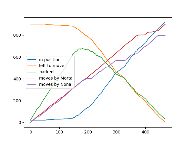
In this example, the first ~ 30% of the elapsed time is used (mainly) for
parking fibres.
Note also the occasional pauses in the movement of each robot (mainly
Nona in this example, purple line) while blocked by the other.
Configuration pauses whenever WHT is slewing [added 5/2022]
Fibre-button magnets: NdFeB (Neo)
Magnet - plate contact: strength of force holding magnet on plate
is reduced by small protruberances on the base of each magnet
(to make it easier to lift magnet off plate).
 (prototype button, from WEAVE-POS-009)
Button-viewing camera: Basler Ace (not to be confused with the
Basler Ace camera in the FPI unit, see below)
Positioner power consumption/dissipation: see under section 9 below
Time taken for robots to halt after covers opened: typically a few sec,
i.e. at next safe opportunity
Mass of fibre positioner (excluding cables, fibres): 628 kg [WEAVE-POS-009]
Mass of cables from PF to Nasmyth cable wrap: ~ 2.7 kg/m [WEAVE-POS-009]
Location of control electronics: electronics room of GRACE Nasmyth enclosure
Tumbler


 (from WEAVE-POS-002, WEAVE-POS-009 and WEAVE-POS-009 respectively)
Positions: MOS plates A and B are at opposite ends (i.e. usually one on sky,
one under fibre positioner), swapped by rotating 180 deg.
An intermediate rotation (90 deg) puts the LIFU on-sky.
Tumbler diameter: 940 mm
Time taken to tumble: 3 min
Tumbler repeatability (with detent): < 0.003 deg [WEAVE-POS-009]
Diameter of central obstruction of telescope by tumbler: 1.8 m
[IDS-820],
implying total 19% vignetting of 4.2 m diameter of M1 [WEAVE-SYS-007]
Diameter of interface plate between tumbler and rotator: 1.8 m
Positioner space envelope (and implied obscuration of M1):
The information below is taken from v1.10 of WEAVE-SPE-004,
or from Dalton et al (2014 SPIE) unless
otherwise stated.
MOS mode
Multiplex: 960 (MOS plate A), 940 (MOS plate B, which also carries mIFUs)
(960 is the number of fibres which can be accepted by the spectrograph)
Minimum separation of fibres on the sky: 60 arcsec
On-sky aperture: 1.3 arcsec (defined by diameter of fibre core)
Positioning accuracy: <~ 0.2 arcsec rms [0.1 arcsec achieved by positioner according to WEAVE-POS-009]
Sky fibres: typically ~ 5 - 10% of the MOS fibres (any of them) will
be deployed as sky fibres
Pre-fibre optics:
 (diverging lens)
 (prism)
(graphics from WEAVE-FIB-001)
(prism)
(graphics from WEAVE-FIB-001)
The diverging lens and prism precede each fibre in the light path.
The diverging lens converts f/2.8 to f/3.2 to reduce injection losses.
Fibre core diameter: 85 micron (silica)
Fibre total diameter, including
silica and polyamide cladding: 120 micron
 (from WEAVE-FIB-001)
Protective tubing for individual fibres: PEEK, OD 0.5 mm, ID 0.34 mm
[WEAVE-POS-009]
Fibre length: ~ 32 m
Fibre throughput (including prism): ~ 0.7 (e.g. WEAVE-FIB-007)
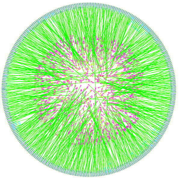
Number of fibre crossings:
typically ~ 8000 when most of the
fibres are deployed:
 (example from WEAVE-POS-002)
MOS/mIFU modes - retractors, bundling of fibres

 (diagrams, and photo of a prototype,
from WEAVE-POS-002, WEAVE-POS-009 and WEAVE-POS-009 respectively)
(diagrams, and photo of a prototype,
from WEAVE-POS-002, WEAVE-POS-009 and WEAVE-POS-009 respectively)
Number of fibres per retractor unit: 6 (3, one behind another, on each side of box) [WEAVE-POS-009]
Number of retractor units: 168 (wedge-shaped) arranged circumferentially
around each plate [WEAVE-POS-009]
Retractor units on plate A: 168 = 160 with 6 MOS fibres each, and 8 with one guide fibre each
Retractor units on plate B: 168 = 150 with 6 MOS fibres each, 8 with 5 MOS plus one guide fibre each, and 10 with 2 mIFU bundles each
Parking of fibres: 6 park plates per retractor box, arranged in 3 tiers
on either side of box, i.e. the parked fibres lie on 3 concentric circles
around the edge of the focal plane (x,y), with the circles being displaced
in the perpendicular direction (z):
 (from WEAVE-POS-002)
The arrangement in tiers is a unique
feature of WEAVE, not used for other MOS.
Reach of fibres: only those in lowest tier can (just) reach beyond centre of
field plate [WEAVE-POS-009]
Number of fibres per bundle
(for sub-slit block): 24
 (from WEAVE-FIB-001)
mIFU mode
Number of mIFUs: 20
Structure of each mIFU: 37 close-packed 1.3-arcsec fibres (same type as used
for MOS-A, MOS-B) in a regular hexagonal array:
 (format of a 37-element
regular hexagonal array)
(format of a 37-element
regular hexagonal array)
Field of view: 11x12 arcsec2
Mimimum separation of mIFUs on the sky: 60 arcsec
Positioning accuracy: 0.5 spaxels [IDS-877]
Pre-mIFU optics: diverging lens + 2-mm prism
Location of mIFUs: MOS-B plate (but it's not possible to observe with
MOS and mIFU fibres simultaneously -
different kilo-fibre bundles)
Area over which deployable: central 1.7-deg diameter (at large radius,
performance is degraded due to non-telecentricity)
Fibre routing to GHRIL
Total number of science fibres (MOS-A, MOS-B, mIFUs, LIFU): ~ 3200
Route: through cable wrap on rotator; along prime-focus support vanes;
down telescope truss; over elevation cable wrap; into GHRIL;
ending at the exchangeable slit units of the spectrograph.
Autoguiding for MOS, mIFUs
Number of guide-fibre bundles (for MOS, mIFUs): 8 per plate (A and B)
Length of guide fibres: ~ 15 m
Field of view: 4.8 arcsec, for each (coherent) bundle (measured by CF/GD 10/22)
(originally expected to be 3.5 arcsec)
Mag of guide stars: 15 < m_GS < 12 (latter limit to avoid saturation)
Filters: there are no slots for filters in the light path to the WEAVE
autoguiders
Detector: standard ING autoguider head
AG3
Detector size (pixels): 1072 x 977
Pixel size: 13 micron
Autoguider unit:
 (from WEAVE-POS-002 and 009 respectively)
MOS-A vs MOS-B configurations: when plate A is configured for science,
the 8 plate-A guide-star fibre bundles
transmit guide-star light to the autoguider
detector, and the 8 plate-B bundles transmit back-illumination from the
autoguider unit to the fibre buttons (for positioning by the robot).
Vice-versa when plate B is configured for science.
Dithering for mIFUs, LIFU
The standard dither patterns for mIFU and LIFU observations
(table taken from version 8.0 of WEAVE-ICD-030,
section 5.4.3.8) are subsets of a hexagonal array (e.g. 3 points, 4 points,
5 points, see appendix C of that document for graphical representations):
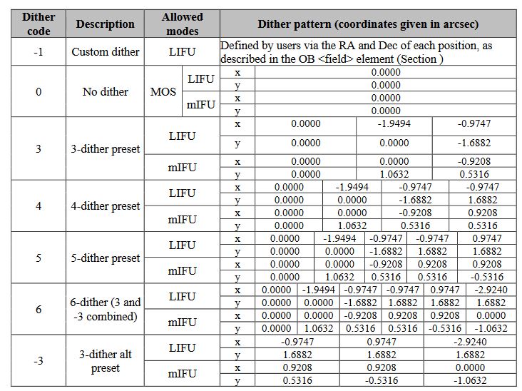
Observations will be processed correctly by CPS (delivering a data cube)
if one of these
dither patterns is used. Observations made with other dither patterns,
e.g. for commissioning / quality-control checks,
will be processed OK by the quick-look pipeline (which may suffice for such
checks) only.
LIFU mode
 (from WEAVE-POS-001 and 009 respectively)
Field of view: 78 x 90 arcsec2 regular
hexagonal array:
Plate scale: 17.8 arcsec/mm
 (from WEAVE-FIB-001)
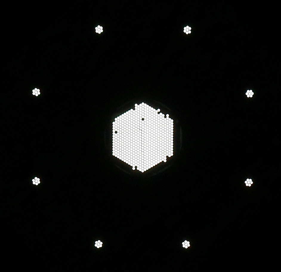 (photo of back-illuminated LIFU by Javier Mendez in May 2022, showing
two dead fibres, a few misplaced fibres at the edge of the science bundle
and the 8 outlying sky-fibre bundles - NB not 6 as on the diagram above)
(photo of back-illuminated LIFU by Javier Mendez in May 2022, showing
two dead fibres, a few misplaced fibres at the edge of the science bundle
and the 8 outlying sky-fibre bundles - NB not 6 as on the diagram above)
 (format of a 547-element
regular hexagonal array)
(format of a 547-element
regular hexagonal array)
Structure: 540 (or 547?) close-packed 2.6-arcsec fibres (plus border of 3 buffer
fibres to hold in place), fill factor 62%,
plus 8 7-fibre bundles for sky (+ offset ING autoguider)
Fibre bundle diameter: 40 mm
Fibre core diameter: 170 micron
Pre-LIFU optics:
air-spaced doublet comprising two BK7 lenses. All surfaces are spherical.
See Fig. 3 of WEAVE-FIB-003 LIFU FDR document.
Location: 90-deg position of tumbler, 20 mm off-axis
Distance from first optical element of the LIFU to its focal plane: 59.0 mm.
Working focal ratio: f/3.2
Plate scale implied: 15.375 arcsec/mm
 (lens diagram from WEAVE-FIB-001) *** to be updated
Size of LIFU box: 400 mm x 120 mm x 200 mm [WEAVE-POS-009]
Dithering options are listed in the table at the end of the last section.
LIFU autoguider
Detector: ING autoguider head
AG2 (E2V47-20 CCD)
Field of view: 3.8 arcmin (CCD is 13.3 mm x 12.7 mm), i.e. 7.4 x bigger than that of the LIFU itself
Pixel size: 13 micron
Pre-autoguider optics: none (apart from window of CCD)
Location: 90-deg position of tumbler, 74 mm off axis in the opposite direction
to the LIFU itself, so the LIFU - autoguider separation is approx 94 mm
= 1673 arcsec
Size of autoguider box: 80 mm x 90 mm x 150 mm
Source of fibre illumination for calibration:
existing unit at Nasmyth level, light fed to PF via Nasmyth flat

(calibration unit,
from WEAVE-WSF-012)
Lamps required: continuum, arc-line
Uniformity of illumination of fibres from flat-field source: < 1% [IDS-1302]
Time required to select a calibration lamp: < 30 sec [IDS-1173]
Lamp warm-up time: < 10 sec
(low- and
high-resolution configurations, from WEAVE-SYS-007).

(mechanical design,
from WEAVE-SYS-007)
The spectrograph will be housed in the refurbished
GHRIL Nasmyth enclosure, in which the same temperature will be maintained all
year round (Don confirms this 1/2019).
 (current layout of enclosure,
from WEAVE-SCI-003)
(current layout of enclosure,
from WEAVE-SCI-003)
The information below is taken from v1.10 of WEAVE-SPE-004, unless
otherwise stated.
Slit-exchange unit

Number of positions: 4 (MOS-A, MOS-B, mIFU, LIFU), arranged in a square
(formerly arranged vertically).
Fibre separation on slit: 35 micron
First component: slit lens (with index-matching fluid between fibre
and first surface)
Arrangement of fibres: 24 per slitlet = sub-slit block,
40 sub-slit blocks (20 per CCD) = 960 fibres total
 (sub-slit block, from WEAVE-FIB-001)
Output f-ratio from fibres: 3.1 [IDS-938]
Back illumination
Geometry: 4 sets of 78 LEDs in slit area,
arranged such that when the slit-exchange
unit is any one of its 4 possible configurations (see above),
the fibres for two of the other configurations are being illuminated by
the LEDs
Collimator
Focal ratio: f/3.1
Diameter of emerging collimated beam: 190 mm
Size, material: 645 mm x 260 mm, Zerodur
Dichroic
Wavelength cut: 590 nm (formerly 600 nm), over ~ 30 nm
(12 nm originally planned)
Transmits: red (and reflects blue)
Angle of incidence: ~ 45 deg
Reflectivity: 97%
Size, material: 390 mm x 308 mm * 25 mm thick (fused silica)
Second-order blocking filter
There is no blocking filter (second order blue light passing into the
red arm will be strongly defocused).
Collimator corrector lenses
Optics: 2 lenses per arm, after the dichroic
Size, material: both are 330 mm x 210 mm (fused silica and PBM2Y respectively)
Anti-reflection coatings: 0.5% reflectivity
Hartmann shutters
Type: two vertical petals, hinged at lowest point
Location: after the collimator corrector lenses in each arm
Functionality: each can be either open or closed, intermediate positions
not possible (they are pneumatically driven)
Main 'fast' shutters
Type: curtain shutter
Location: a few mm after (and in the same unit as) the Hartmann shutters
(there's no shutter close to the CCDs),
Direction of movement: horizontal (wavelength direction)
Speed: 0.8 sec? (aim for even illumination, to within +- 0.3 sec)
VPH gratings
Blue arm: low-res (1385 lines/mm) + high-res 1 (blue) (3580 l/mm) + high-res 2
(blue-green) (3056 l/mm) = total of 3 VPH
Red arm: low-res (876 l/mm) + high-res 1 (2431 l/mm) = total of 2 VPH
Incident angles: 20 deg (low-res), 51.6 deg (high-res 1 and 2)
Configuration: Littrow (indicent and diffraction angles are equal)
Size?: 192 mm x 202 mm (low-res), 190 mm x 309 mm (high-res 1, 2)
Thickness: 30 mm (low-res), 40 mm (high-res)
Dispersion direction: horizontal, i.e. parallel to the surface of the optical bench in GHRIL
Camera-arm rotation
Spectrograph footprint: 2.1 m x 1.9 m in low-res mode; 1.7 m x 1.7 m in high-res mode
Cameras
f-ratio: 1.8
Optics in each arm: 8 lenses (same in each arm, but different spacings),
plus cryostat window. Only one of the 8 lenses is aspheric
Anti-reflection coatings: camera lenses have different coatings,
0.3% reflectivity
Sizes of lenses 1-8: finished diameters 235 - 320 mm
Materials of lenses 1-8:
Ohara PBM2Y, PBL1Y, S-FPL51, PBL1Y, S-FPL51, PBM2Y, PBM2Y, S-LAL9
Sizes and material of cryostat window: diameter 180 mm, thickness 15 mm,
fused silica
Clearance between window and detector: 3 mm
Distance from last surface of camera optics to cryostat window: 5 - 7 mm
(see below)
Detector focus/tilt (for different spectrograph configurations)
What moves: detector cryostat + window only
Focus: ~ 5 - 7 mm
Tilt (about vertical axis): ~ +- 0.3 deg (no movement is possible in 'tip' direction - this was fixed during manufacture, and can't be adjusted even during
integration of the detectors with the spectrograph)
Throughput of spectrograph alone
400 - 600 nm: 0.66 (excluding FRD losses)
600 - 950 nm: 0.67 (excluding FRD losses)
Mass and size of spectrograph
Mass: 2200 kg (including table)
Size: 3.0 m width x 2.0 m depth x 1.8 m height
The information below is taken from v1.10 of WEAVE-SPE-004,
and v1.0 of WEAVE-RFC-004 (includes CCD231-C6 datasheet),
unless otherwise stated.
Geometry
Pixels: two 6144 x 6160 CCDs in each arm ~ 90 mm x 180 mm
(6144 = 6 * 2^10)
Used pixels:
8192 (spectroscopic, probably x, as of April 2021) *
6144 (spatial, probably y)
= 123 mm x 92 mm
Inter-CCD gap: 2.5 mm (TBC) in spectral direction, equivalent to 170 pixels [WEAVE-RFC-004]
Pixel size: 15 micron
Flatness: 40 micron peak-to-valley
Other detector parameters
Type: EEV CCD231-C6, deep-depletion, 4 read outputs
Read noise: 2.5 e- (max 4.0 e-)
Dark current: < 0.1 e-/hour
Fringing: ~ 0.2% over 680 - 1000 nm
Reflectivity: 13.5%
Readout speed: 60 sec
Bad pixels: <0.0025% (probably)
Columns with > 20 bad pixels: <2 [IDS-1044]
CTE in serial direction: >0.99999 [IDS-1048]
CTE in parallel direction: >0.999995 [IDS-1049]
Filling cryostats with LN2
Hold time:
currently (11/21) being filled every 11 hours, but hold time is probably longer.
[To be checked.]
Position for filling: LR or HR or any? [To be checked]
Minimum length of time after filling, before arm movement: [To be checked]
The information below is taken from v1.10 of WEAVE-SPE-004, unless
otherwise stated.
Spectroscopic resolution and wavelength ranges
MOS/mIFU low-res mode: R = 5000 (60 km/sec), blue arm 366 - 606 nm, red arm 579 - 959 nm
MOS/mIFU high-res mode: R = 20000 (15 km/sec), blue arm 404 - 465 nm or 473 - 545 nm, red arm 595 - 685 nm
In LIFU mode, the wavelength ranges are the same as quoted for MOS/mIFU
above, but the spectroscopic resolutions R are lower by a factor of two (due to the fibres having twice the diameter of the MOS fibres), R = 2500 and 10000 in
low-res and high-res modes respectively.
Overall wavelength range: 366 - 959 nm
Scale in low-res mode: ~ 0.030 (blue) and 0.048 (red) nm/pix
Scale in high-res mode: ~ 0.0076, 0.0090 (blue) and 0.011 (red) nm/pix
Inter-CCD gap (170 pixels, TBC) [measured from Remko's 3/2017 updates of
figures from WEAVE-RFC-004]:
Low-res blue: 548 - 555 nm (7 nm)
Low-res red: 758 - 768 nm (10 nm, includes atmospheric A band at 759.4 nm)
High-res blue 1 (404 - 465 nm VPH): 452.3 - 454.0 nm (1.7 nm)
High-res blue 2 (473 - 545 nm VPH): 529.7 - 531.6 nm (1.9 nm)
High-res red 639.8 - 642.5 nm (2.7 nm)
Remko notes that manufacturing errors could introduce changes in the start
and end wavelengths of the gap, by ~ 20% of gap width.
Location of spectra (horizontal lines)
relative to area of 2-CCD mosaic and relative
to the inter-CCD gaps (click on image to see the latter), all from v1.0 of
WEAVE-RFC-004:
Low-resolution blue and red respectively - the start
and end wavelengths of the central gap do not depend on fibre number
(this is by design).
Ignore the large-scale 'fringing' pattern in these figures.
High-resolution blue 1 (a figure for high-res blue 2 is not available)
and red respectively - the start
and end wavelengths of the gap do depend on fibre number.
Wavelength location of spectral gaps for high-resolution configurations
blue 1 and red (from Remko 3/17):
The shaded area indicates the location of the gap in wavelength (vertical axis)
as a function of fibre number (horizontal axis), for each of the
high-resolution blue 1 and high-resolution red configurations.
For high-res blue 2, click
here (from Remko 3/17,
slightly different format).
The gap wavelength ranges quoted above for high-resolution modes are
taken from these three plots.
Sampling: > 3 pixels
Stability: < 2% change in resolution
over one hour if GHRIL temperature stable to < 1 degC
Spatial resolution
Sampling: 3.3 pixels
Variation in spatial profile (FWHM of lines) with time:
< 5% over 1 hour [IDS-1037]
Spacing of fibres on CCD in spatial direction, in MOS/mIFU modes:
6.0 pixels (= CCD dimension 6000 / 1000 fibres) = FWHM 3.3 pixels + separation 2.7 pixels between fibres
In LIFU mode, the spacing between fibres in the spatial direction is 9 pixels
(with slightly larger gaps between the groups of fibres in individual slitlets).
Cross-talk
Between adjacent fibres: < 0.5%
Stray light contribution from any one object to spectrum of any other: < 0.5%
(see notes in WEAVE-SPE-004, table 2.1, for a definition)
Detector ghost images
Intensity: < 1% integrated flux of source object [check?]
Wavelength calibration
Accuracy: < 0.05 pix [IDS-1303]
Stability: < 0.1 pix over 1 hour [IDS-1304]
Flat-field illumination of CCD
Light source: 3 LEDs (different colours) insertable in area of VPH
in each arm
Flux calibration
Accuracy: < 5% fibre-to-fibre [IDS-1305]
The information below is taken from WEAVE-SYS-007, unless
otherwise stated.
Overall throughput of WHT+WEAVE
Low-res mode, 450 - 850 nm: ~ 0.25 (taking into account all components
along light path from bottom of atmosphere to detector):
(plot of throughput vs
wavelength, from WEAVE-SYS-007)
High-res mode, ~ 0.10 - 0.25, depending on wavelength:
 (plots for blue and red respectively, from WEAVE-SYS-007)
Operating conditions
Dome temperature: -5 - 25 degC [IDS-608]
GHRIL temperature: 10 - 18 degC [IDS-429] (will actually be maintained
at the same temperature all year, see under 6. above)
Dome humidity: 0 - 100% [IDS-610]
GHRIL humidity: 20 - 40% [IDS-430]
Pressure: 745 - 785 mB [IDS-611]
Impact on environment
Heat dissipation by WEAVE at WHT top-end:
600 W average (=
380 W from robot positioner,
150 W from rotator motor,
30 W from focus translation system,
40 W from ADC motors)
[WEAVE-SYS-036]
Data flow
(flow diagram, from WEAVE-SYS-10)
Observations per night: probably ~ 10 fields = 1000s spectra in MOS mode
Data rate: ~ 10s Gbyte/night in MOS mode
Timescale for archiving raw data off-island: ~ 12 hours
Example of a
current
WHT FITS header (for ACAM)
Surveys
WEAVE first light: expected 2022
Number of spectra required for currently-planned surveys: ~ 15 million
Duration of currently-planned surveys: ~ 5 years
Fraction of WHT nights available for WEAVE surveys ~ 0.7
Median expected observing elevation: 65 deg (range mostly 50 - 80 deg), see
plot:
obtained by Cecilia and Lilian during tests of the scheduler with a realistic set of targets
(T1 - T6 refer to tests with different sets of input data).
Length of OB: 1 hour (including all overheads)
Typical exposure time 3 * 17 min (+ calbrations and overheads => total
1 hour
Exposure increased during observing only in event of loss of counts due to known cause e.g. bad weather.
Information about observing conditions can be found
on the site-quality page. Summary:
Weather: clear sky ~ 75% of night hours (with reduced transparency during
occasional dust storms).
Seeing: median 0.80 arcsec April - November (8 months), and 1.07 arcsec
December - March (4 months).
Sky brightness: V = 21.9 mag/arcsec^2 at high elevation, high galactic latitude,
high ecliptic latitude and sunspot minimum,
similar to that at the principal observatory sites in Chile and Hawaii.
Solar activity is currently rising, last sunspot minimum was ~ end 2019.
Apocalyptic volcanic activity: occasional.
ADC - atmospheric-dispersion corrector
CTE - charge-transfer efficiency
e- - electron
f/ - focal ratio
FPI - focal-plane imager
GHRIL - one of the WHT's two Nasmyth enclosures (abbreviation of 'ground-based
   high-resolution imaging laboratory')
GRACE - one of the WHT's two Nasmyth enclosures
ID - inside diameter
IDS - Instrument Development Specification
l/mm - lines/mm
LED - light-emitting diode
LIFU - Large integral-field unit
M1 - WHT primary mirror
mIFUs - Multiple integral-field units
MOS-A, MOS-B - two (multi-object spectrograph) plates (swapped by rotating the tumbler)
 on which the sky-facing fibre ends are mounted
OD - outside diameter
PFC - prime-focus corrector
rms - root mean-square
TBC - to be confirmed
VPH - volume phase holographic grating
WEAVE - WHT enhanced-area velocity explorer
WHT - William Herschel Telescope
The above lists excludes standard abbreviations for units, e.g.
deg, Gbyte, nm, t.
Click here for consortium logos.


