GLAS Setup/Observing Recipe
Version 2009 May 17
The setup/observing recipes below are intended for ING support staff.
For hints on solving common problems, see the
NAOMI troubleshooting guide.
More detail about mirror-flattening can be found in the
NGS mirror-flattening recipe.
These recipes supercede the old NGS
NAOMI setup/observing recipe.
Contents
Links to other useful documents:
-
GLAS:
Laser power,
Jure's pages,
GRACE logbook,
GRACE environmental control,
ops-team home page (DE NAOMI, OASIS, INGRID, LDSO checklists),
Tip-tilt user manual,
Measuring on-sky offsets,
Optics,
Presentations,
Wiki (logs, how-tos etc.),
Commissioning images,
Switching between GLAS/sextans and NAOMI/lpss42
- NAOMI:
Home page,
old
Setup/observing recipe,
AO acquisition tool,
PSF performance,
Technical information,
Troubleshooting,
Useful numbers
- Science instruments:
INGRID,
OASIS,
OASIS observing recipe,
OSCA
-
Sam's
AO internal webpages (categorised lists of links)
- Other:
Weather
GLAS is a 5149-A Rayleigh laser guide star (equivalent mag ~ 9.5)
for use with the NAOMI adaptive-optics system.
It is created by a 15-W beam (10 W as of Dec 2008)
of laser light launched from a small telescope mounted behind the WHT secondary mirror,
and focused to a 10-cm spot at an altitude ~ 15 km
(i.e. subtended angle ~ 1 arcsec).
GLAS samples the atmospheric turbulence at altitudes below 15 km (this turbulence often dominates the seeing
at the WHT), hence the name: Ground-layer Laser Adaptive-optics System (GLAS).
The AO system is currently operated in 4 different modes:
- LGS (GLAS) + NGS (L3)
- NGS (L3) tip-tilt/autoguiding only
- NGS (EEV39) high-order (NAOMI's original operating mode)
- NGS (EEV39) tip-tilt/autoguiding only
It is possible to switch between modes 1 and 2 during the night.
Switching between modes 1 (or 2) and 3 (or 4) is not possible
during the night.
While the laser is powered on, nobody should enter the dome without
wearing the appropraite safety glasses (the ones in individual metal boxes
labelled 'GLAS').
The safety glasses should be worn at all times in the dome,
including in GRACE.
The laser is mounted on the top-end ring of the WHT, feeding the
beam-launch telescope behind the secondary mirror.
The intense 5149-A light from the laser is an eye-safety hazard anywhere
in the dome area, particularly if any part of the beam is relected
(accidentally, or intentionally) off the inside surface of the dome.
Access to the dome is strictly controlled (by the laser safety duty officer)
during observing.
Detailed safety documents are linked from
Jure's pages.
Review current status of AO system
- Review any new entries in
- The NAOMI logbook (record of
daily mirror-flattening etc.) - it's usually somewhere near the AO
display screens;
- The daily GLAS checklist, filled in each day by the DE
(old copies filed in ring binder, usually above the AO screens);
- The
GRACE logbook (record of changes in GRACE).
In GRACE
- Remove the mirror covers, check that the derotator cover is on/off
as required, check the light path for other covers (e.g. of the LGS lens)
or obstructions.
- Check that the required pinhole is in front of the simplex lamp (almost
always the 2-micron pinhole).
- Check that the humidity is >~ 30% (usually the ops team watch out for this).
Login to aodisplay screens at right-hand end of control desk
- Click on the whtobs icon, and enter the usual password for whtobs.
The 'exceed' windows manager will be brought up.
The left and right screens are for 8-bit and 24-bit windows
respectively.
(NB if you log out of aodisplay1 first, for a clean startup,
open the WFS and SG loops on the top gui C40s page. Anything
else to close down?)
- Double click on the 8-bit icon to bring up an xwindow.
Type obssys. Use this window for messy things like GlasRestart.
It will churn out endless error messages.
- Bring up another 8-bit xwindow. Type obssys.
- Double click on the 16-bit icon to bring up an xwindow on
the right-hand screen. Type obssys.
- Computers in use:
- sextans - most of the user's interaction is with this
- aocontrol1 - runs low-level things, not normally necessary to
interact with it
- lpss94 - used only for running up the codeso gui
- lpss42 - backup for lpss94?
Start top gui
-
Type TopGuiGlas &. This should bring up top gui.
If not, type GlasRestart in the other
xwindow, then TopGuiGlas & in this one.
TopGuiGlas also brings up the small medm window,
which reserves colour cells.
Once this medm window is running, it suffices to type topgui &
when you need to restart top gui (which will be often).
If you suspect a problem with the WFSD:
- In an 8-bit xterm,
type WFS Start, then WFS Status, check frame number is incrementing.
- On the top gui SDSU page, under LGS camera control,
click on re-init (necessary?)
- On the top gui C40s page, start the camera framing, close the SG loop,
check that SG gain = 0.8.
Start the fisba display
- Check that the fisba display on the screen
above aodisplay is active. If not,
click on the 'FISBA PC' icon. Minimise the PC Anywhere window.
If the fisba display won't come up:
- Close the FISBA session on
the PC Anywhere window
- Click on the 'microshape' icon
to restart
- Click and drag the fisba display to centre it (on the screen
above the aodisplay screens)
- Click on intensity, select zoom 3.
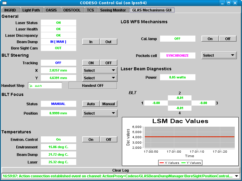
Start the codeso gui (for control of OASIS, INGRID, GLAS etc.)
- Click on the 'OASIS GUI' icon, to bring up the codeso control gui.
If this doesn't work:
- Click on 'lpss94' icon to bring up an lpss94 session:
- obssys
- startoasisgui
- If the boxes on the gui come up in red (error state),
try: startoasisserver
- Click here for a snapshot of the GLAS control gui.
- Click
here for Sergio Pico's GLAS mechanisms
user manual.
- If the all the entries on the glas mechs gui turn red,
type in an lpss94 window: startglascomms
- It's convenient to have a second copy of the codeso gui on the whticsdisplay1
screens: ssh -X whtobs@lpss94, obssys, startoasisgui.
Display the TT gui
Click on the 'TT gui' icon on aodisplay screen 1.
The TT gui can be brought up in any browser window, and the TO will
probably bring up a copy at his/her screen, for use when acquiring the
NGS. One can be brought up on taurus as well, if required.
At whticsdisplay1 (WHTICS window)
- If changing from LGS mode to NGS, or vice versa, type
setAOmode NGS or
setAOmode LGS
at the WHT instrument-control prompt.
On subsequent days of the NGS (or LGS) run, it is not necessary to type
this command.
- Check that the light-path mimic is reporting the NGS WFS and FSM
appropriately.
To kill a window on aodisplay, double-click on the 'xkill' icon,
wait for the box-shaped cursor to appear,
drag the cursor across to the window to be deleted, and click
with the left button.
(If the icon is not present, type xkill in any xterm,
a skull and cross-bones cursor appears,
click on the appropriate window with the left mouse
button. If your change you mind, click on one of the other mouse
buttons.)
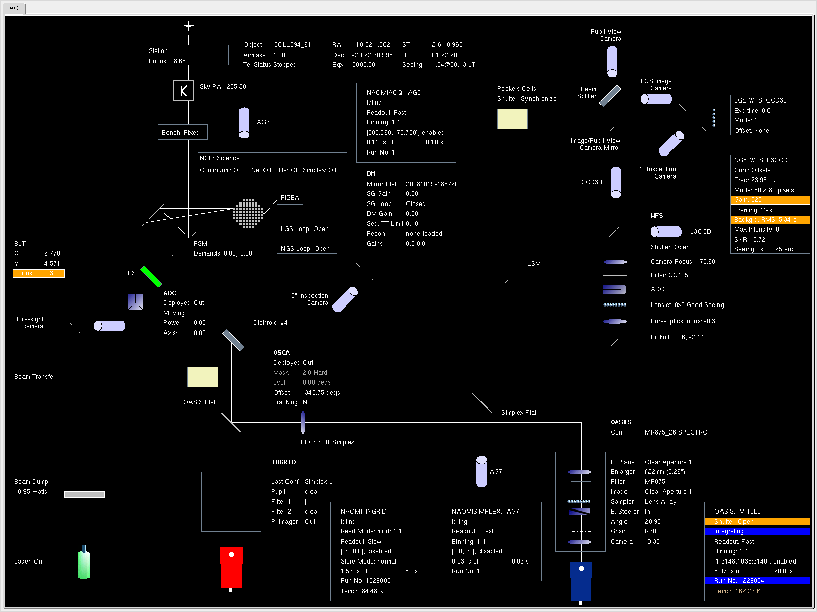
The AO light-path mimic is displayed permanently on the whticspc
monitor in the angle of the control desk.
If for some reason it has to be restarted,
type on taurus:
ssh whtobs@whticspc startAOmimic stop
which kills the mimic. Then:
ssh whtobs@whticspc startAOmimic start
The laser is started up by the daytime engineering staff (ideally at
least 6 hours before observing).
The DEs' laser start-up and laser/BLT checks instructions
can be found on the
ops-team home page.
Pockels cell:
for light from the laser calibration source to reach the LGS-WFS
via the Laser Steering Mirror (LSM)
and the Pockels cell shutter, the latter must be powered on.
Probably it's not necessary to check it, but just in case it's off,
this is the procedure:
- Power up the high voltage unit located in the electronics room
(ask an engineer).
- On top of the Pockels-cell
shutter unit (the square double-decker arrangement
on the optical bench with optics sandwiched in between)
sits a switch unit.
This must be 'on' and the top switch in the correct polarity.
At the glas-mechanisms gui in the control room, switch to 'synchronise'
(if it won't change, switch to 'open' first, then 'synchronise').
The
laser traffic-control web page can be brought up,
on e.g. the whtdrpc1 screen, by
typing ltcs in the browser window.
Useful cameras:
The mirror-flattening ensures
that a point source at infinity (simulated by the pinhole
in the Nasmyth calibration unit) will be imaged sharply on
the science detector.
The laser, white-light
and simplex procedures are documented in detail in the
NGS mirror-flattening recipes
The phrase below 'in the usual way' means as described in these
recipes.
View the WFS spots on the NGS WFS
- Have the pickoff mirror on-axis (x ~ y ~ 0)
- NCU to simplex position
- 50:50 or Barr IR dichroic
- Simplex lamp on, iris -150
- From top gui, put in the good-seeing lenslet
- Check that the NGS WFS camera focus is 172 (probably it already is).
NB this is the 'demand' position. The 'actual' position recorded
on the epics gui may be different, and changes with the x,y position
of the probe.
- On the TT gui:
- Select 'offsets' option from the configuration menu on TT gui
- Check that the configuration is 80*80 pixels,
exposure time 5 msec, gain 220
The spots should have peak values of several thousands counts
(position cursor over them to check)
Bring in any wayward spots
... in the usual way, using the x,y controls
on the DM page on top gui (this slightly complicated by the
TT gui display not having a numbered overlay).
Laser-flatten
- Float the bench (takes ~ 5 min)
- Laser-flatten in the usual way.
Usually, there's no need to turn down the air-conditioning, although it
may help in some circumstances, e.g. if there are also vibrations from the
oil pumps (which one might not want to switch off, if on-sky).
If in LGS mode...
If in NGS mode...
Simplex
Simplex for each observing configuration (at least optical/50:50-dichroic
and
IR/IR-dichroic, if both are to be used).
Consult the relevant webpages for OASIS, INGRID and OSCA.
In particular, if using OASIS, make sure that the correct filter
focus offset is known for each filter to be used, i.e. inspect
the simplexed pinhole image though each filter, and if necessary,
determine the best value of filter focus (on the codeso light-path
gui). The simplexed pinhole image should have FWHM ~< 2 pixels on OASIS in
imaging mode.
In GRACE
- Check that the derotator cover is off.
Check the laser power
- On the GLAS mechanisms gui, with the beam dump in, check the
laser power. It should be between 7 and 20 W
(12/08 was ~ 10 W).
Check the configuration of the LGS loop
- Check the exposure time on the LGS WFS
- Check that top gui is in LGS mode (usually, it will be),
not NGS mode.
- On the glas-mechanisms gui, check that the Pockels cell
is set to 'synchronise'. (It's also instructive to watch what happens
on the LGS WFS when this is switched between 'open' and 'closed'
when on-sky.)
- The reconstructor should be loaded automatically, i.e. it should say
'running' on the left-hand page of topgui. If not,
then on the real-time page of top gui (clock icon), click on load, select
from the menu the NAOMI reconstructor (for NGS mode, use ELECTRA,
according to Jure 6/09).
- Check on topgui's real-time page that the
gains are set to 110, 105,
and that the DM gain ('Loop gain' on topgui?) is set to 0.3.
Note that the old reconstructor test (shifting the pinhole, with
the LGS loop closed) cannot now be carried out.
Check the configuration of the NGS loop
- From top gui, put the doublet lens in the light path
(although it's often useful to start the night with the
good-seeing lenslet, to check the appearance of the seeing).
- Check that the black autoguider switch (on the TO section of the
desk) is set to 'Tiptilt PC'.
- Take a bias frame for each NGS WFS configuration (including gain
settings) to be used, by selecting the configuration at the
TT gui, making sure there's no light falling on the detector,
and clicking on bias (takes a few sec).
This is best done in the afternoon, but
in practice, it's also straightforward to do this during the night,
after selecting a new configuration.
NB the NGS WFS shutter doesn't work, so if taking bias frames
on sky, make sure that no starlight is falling on the WFS.
NB it takes a long time to obtain the bias frame for
autoguiding modes.
The aim of these checks is to ensure that the laser is firing on-sky, and
that the laser guide star is being imaged by the LGS WFS.
Check that the laser is on-sky
- Move NCU slide to science position.
- Set the WHT tracking, ideally by pointing to a 9-mag star, for later
use.
- Make sure the TO has physically unlocked the 'beam dump interlock' on the
old engineering console.
-
Switch the beam dump out.
(If it switches back in, with message 'LTCS coll', this means it thinks
a collision with another telescope has been detected, but
this may not be true - if there's no collision indicated on the
LTCS page, switch the beam dump back out.)
- Check the laser beam is visible on the
video camera
viewing the dome aperture.
Check the laser return
- Set the WHT focus to 98.65 (used 5/08 and 12/08) (98.45 Aug/Sep 2007,
98.40 Jan 08).
-
View the 8-arcsec stop in the LGS WFS light path with the
inspection camera.
This stop precedes the Pockels cell.
If the laser light is already passing through the spot, you will
usually see some scattered light (fanning out radially) around
the hole in the stop.
If not, the laser spot will usually be visible somewhere in the imaged
field.
NB the scattered light is a useful cirrus monitor. When there is more than
a few tenths of a mag of cirrus, a highly-defocused image of the laser spot
(pupil image, showing secondary vanes) is visible.
If one is observing close to the moon, scattered moonlight will
be visible (halo).
- Use the handset
to tweak the BLT x,y position in 0.05 steps, to steer the
spot symmetrically behind the stop
(NB the coordinate system is not orthogonal to the WFS, and the
orientation will depend on the derotator positon angle).
The x,y values were 3.1559, 4.5396 in 5/08
(and were 3.15, 4.61 in 4/08; 2.90, 4.57 in 9/07; 2.8, 4.5 on 21/12/08).
Refer to the GLAS log-sheets.
Check that the BLT tracking is back on.
- The spot may then also be visible on the 4-arcsec camera just in front
of the LGS WFS, although it will be much fainter (time-gated by
Pockels cell, and poorer reflecting
surface).
Check the laser focus
- It should not usually be necessary to change the BLT focus.
A value of 9.0 was used Feb + Apr 2009 (9.3 measured 14/9/08 and used 12/08;
9.6 in 5/08 and 25/9/07).
If a tweak *is* necessary, adjust it so as to
minimise the size of the spots on the LGS WFS.
Check detection of the laser on the LGS WFS
- Select
LGS WFS mode 1 from top gui, or with WFS SetGlasMode 1
[this step is probably not necessary - to be confirmed]
The fast readout should be selected.
- If necessary,
tweak the BLT x,y in small steps (0.01) to approximately
centre it on the
LGS WFS.
The centring doesn't have to be very accurate; once the
LGS WFS and BLT-tracking loops are closed, the spots should
centre themselves.
NB on the LGS WFS, there are only 8*8 spots (and the
bottom four are very faint), due to vignetting.
Each spot is accompanied by a ~ 1%? ghost due to reflection from the
back surface of the beam-splitter, and a brighter, radially-displaced,
ghost arising in the LGS WFS arm.
Check laser range and duration (not normally required)
See Appendix 4.
Check the laser alignment (not normally required)
See Appendex 4.
The importance of the telescope focus
requires some explanation.
The LGS-WFS has a fixed focus position
where the reference is the laser calibration source.
The laser
calibration source is conjugated to some fixed distance from the
telescope (typically, 15km).
That distance is defined by the timing
delay set for the Pockels cell shutter.
If the WHT focus is not at the
correct value then this will affect also the laser beacon focus and
hence introduce an unwanted focus term on the LGS-WFS.
The system will
want to take out this term by demanding the DM to correct for
it.
Whether there is a focus problem can be tested by checking the
focus demand from the LGS-WFS in open-loop and closed-loop mode.
There
should be no difference between the two situations.
To get readout of
the focus term, type PrintFocus 10.
The output is in (approximately)
the same scale of the WHT focus.
If there is a significant difference,
the WHT focus may be wrong, or the range-gate distance must be
adjusted.
At the start of the night, the offsets on the LGS WFS must be
measured.
These offsets serve the same function as those used in NGS mode,
but are measured differently.
A different set of on-sky offsets (measured using
appropriate simplex-lamp calibration
offsets) is needed for each configuration of mirror-flat and
dichroic, typically: INGRID-simplexed/IR-dichroic and
AG7-simplexed/50:50 dichroic.
For optimum performance, the offsets also have to be measured
at each elevation (+- ~ 10 deg?) at which observations
will be made (whether +- 10 deg is OK is under investigation).
See
here for a discussion of how the LGS-offsets procedure works.
The instructions below, for measuring the offsets, are adapted from
Jure's 4/08 .pdf offsets
recipe.
*** Note that the offsets are *not* reloaded after a GlasRestart.
Configure the L3 camera, measure a bias frame
If the bias is not subtracted,
there will be a significant gradient across the images, which will
compromise the centroiding and make the measured offsets useless.
The bias frame needs to be measured only once per night.
- Make sure no light is reaching the L3 CCD.
The WFS shutter is not currently working (it's taped open), so e.g.
from the codeso light-path gui, move the NCU to the simplex
position, and make sure the calibration lamp is off.
- On the TT gui, make sure that bias subtraction is off,
put the camera in the offsets conguration (80*80 pixel readout mode,
gain 220, exposure time 5 msec).
Check that no light is reaching the L3 CCD.
- On the TT gui, click on the 'Take bias' button. The buttons greys out
while it's taking the 500 images (~ 20 sec).
A median image will automatically be derived and stored, and called
upon whenever you hit 'subtract bias' in the relevant configuration.
Take calibration offsets on L3
Calibration offsets are taken using the calibration lamp as the
light source.
They are equivalent to
the offsets normally taken in NGS AO mode on the CCD39 camera.
These offsets are used as a
reference when we take on-sky offsets and the offsets on the LGS are
then tuned so that the on-sky
NGS (natural guide star) offsets exactly match the calibration offsets.
When this happens, we know
that the LGS offsets are such that they produce an optimal image.
This procedure only needs to be done once for each mirror flat.
If the mirror is re-flattened during the night,
it's necessary to repeat the calibration offsets.
- NCU in simplex position, correct dichroic in place,
simplex lamps on, set iris to -150 [*** check]
- Activate bias subtraction on L3. This is essential!
Check that L3 is in 80*80 mode, with gain 220, and 5-ms exposure
time.
- You should see spots on the WFS. If they are strongly decentred,
move the pickoff probe so that they are approximately centred.
Check for saturation or insufficient signal.
- At an xterm window, run L3AutoCentreProbe.py.
This will centre the spots after a few iterations.
- Check again that gain is 220, exp time is 5 msec, bias subtraction
is activated.
- Bring up Jure's GLAS offsets gui by clicking on the GLAS offsets
icon, or by typing GLASoffsets at an xterm window.
- On the GLASoffsets gui:
- Set the number of images to 1000 and press
return (don't forget to press return!).
- Click on the label 'Measure calibration offsets from L3'.
- Click on Run button and wait ~ 40 sec.
A file name will appear next to the NGS calibration label.
- Click on the tick box left of the 'NGS calibration' label
and the centroids of the calibration spots will be displayed.
- Write the name of the calibration file in the NAOMI logbook.
Prepare for on-sky offsets
- On top gui, select the 8*8 good-seeing lenslet.
- Make sure on TopGui that both NGS and LGS loops are open.
- Point the telescope to a star of mag 8 - 9.
- Switch the NCU to the Acq/Arc position, and use the acquisition tool
to image the star on AG3 and acquire it on the L3 CCD,
then switch the NCU to the science position (spots should be visible on the
NGS WFS).
- Remove the beam dump, check laser is propagating on-sky.
- On the GLASoffsets gui, click on the ZeroC40offsets button
(if this is the first attempt at measuring the offsets),
then click on Run.
This will zero the on-sky offsets in the C40s and create a file with
zero offests. If this takes more than a few sec, there is
something wrong: quit from the gui, kill any other versions of
the gui that are open, restart the gui.
- Ask the TO to centre the NGS spots on L3 by moving the telescope.
- On the TT gui, close the TT and autoguide loops.
Ask the
TO to autoguide on pixel 500 500. Alternatively, at a taurus
prompt, type obssys, then return, then:
user "autoguider on 500 500"
-
Check that
the spot pattern is centred on the image, and fixed.
Using the realtime controid plotter on the TT gui, check that the centroids
are not oscillating (if they are, try reducing the gain, and use
proportional loop-control method, e.g. PID with P 0.4 -> 0.2??).
- Acquire the LGS (one spot in each sub-aperture). From top gui,
close the LGS loop.
Once the loop is closed, the spots will appear stiffer (will wander about less).
Make sure that the BLT-to-LSM offload is active.
Observe the LSM demands until they appear to stabilise close to
the central position.
Measure the offsets on-sky
The configuration at this point must be:
- Laser is propagated on-sky, LGS loop is closed, LSM demands are
not saturated.
- L3 is in offsets mode (80*80 pixel, gain 220,
exposure time 5 msec), with bias subtraction activated.
- NGS spots are centred on L3 image, NGS loop is closed and stable.
The WHT is in guiding mode and receiving packets.
On the GLASoffsets gui:
- Click on the tick boxes left
of the labels 'NGS calibration' and 'NGS on-sky last'.
Set 'No.of' to 1500, and check that the x and y gain values lie
between -0.5 and -1.
- Iterate the following two steps until the 'average error'
is better than 3%:
- Click on label 'Measure on-sky offsets from L3'.
- Click on 'Run' and wait ~ 80 sec. If the appropriate tick box is
checked, avarge spot positions will be displayed alongside the calibration
spots.
An 'Average error' will be displayed. In the first iteration, this is
typically 6 - 12%. When it reaches 3%, the offsets are satisfactory,
skip to the item 'Write down...' below.
- Click on 'Subtract NGS error from C40 offsets', then on 'Run.
This will subtract the (weighted) NGS offsets from the C40 offsets
and apply the difference to the C40 system.
(If this takes more than a few sec, there is
something wrong, see above under 'Prepare for on-sky offsets'
for a solution.)
In the next iteration, the new offsets will be used by the AO system.
Return to step 1 above.
- Write down the on-sky offsets file name [which one??] in the NAOMI logbook
- Open the NGS and LGS loops, stop autoguiding.
- Put in the beam dump.
- Move the WFS lenslet wheel to the doublet position.
Re-measuring offsets
If for some reason the procedure fails, then after restarting topgui,
you will need to reload e.g. the previously-loaded NGS calibration
offsets. Click with the cursor just to the right of
'NGS calibration' on the GLASoffsets gui, and a menu of filenames will come up.
*BEWARE* - note that if measuring offsets for a different mirror flat
/ dichroic, you need to measure (or load up) the NGS calibration offsets
for that configuration - you can't use the ones obtained for any other
configuration.
The offsets are stored in /software/Electra/save/GLASoffsets.
Reloading offsets
After a GlasRestart, no LGS offsets will be loaded, you need to load them
with either (worked 12/08):
- Go to the WFS page on top gui
- Under LGS offsets, click 'Load'.
-
The menu which pops up will point to the NGS offsets directory.
Under 'Filter', erase 'WFScentroidOffsets' (you'll need a great deal
of patience here) and replace it with
'GLASoffsets', then hit return.
- Locate the required file in the menu, and click on 'OK'
- Sometimes the file doesn't load. Try GLASrestart (twice, to be
on the safe side), then repeat the above.
or (last tried 5/08) e.g.:
- WFS SetWFSoffsets C4020080515-000311.wcnof
[needs no path name??]
(doesn't update offsets gui)
or (maybe):
- Use Jure's offsets gui [needs confirmation]
The TT loop is controlled
from
Jure's TT control page,
which is documented in
the
TT users' guide.
Below is a screen dump of the top part of the page in camera mode.
Useful real-time plots can be obtained by switching to 'plotter'
mode.
The NGS WFS section of top gui's
light-path page includes a configuration menu, but this doesn't
work, and selecting one of the options might have unexpected effects.
Click on 'Show NGS' on the left-hand page of top gui
to display (slow update) the TT image.
The TT and autoguide loops can be opened or closed from the buttons
from the buttons on the TT gui. The TT and autoguide
buttons on topgui don't work.
Once the loop is closed, ask the TO to start
guiding at the TCS (auto on 500 500).
The loop status is reflected on the TT gui, on top gui, on the
AO light-path mimic, and in the FITS headers (and observing log).
Note that a log created by the TT control
system can be found at e.g. tiptilt/2007xxyy. A new log is started every
day at 12 UT. Severe problems are colour coded in red.
A number of parameters can be specified on the TT gui.
The exposure time, frame size and control method are all
determined by the selected configuration, usually '100 Hz'.
The frame size is usually 16x16 pixels, and the control method PID,
with P = 0.4, I = 0.5, D = 1.
For faint stars, the gain is usually 255.
True exposure time = that on gui + readout time.
The centroiding method is 'thresholded weighted', threshold is
in sigma, centroiding uses 4 x 4 pixels.
The display 'update frequency' must be 1 or larger (default is 0).
Note that the
tiptilt real time process is automatically started again if it stopped
(e.g. with the 'kill' button on the GUI). If the controller is
switched off, the RT process goes to sleep. It will recover when the
controller is switched on again.
x and y are reversed relative to topgui,
and 1 unit of TT movement = 1/8 unit of TT movement on top gui.
Click on topgui NGS display to bring up tit-tilt display at centre
of main WFS display (currently not very useful, intensity levels are wrong).
The scale is 0.25 arcsec/pixel?
Acquire a bright star, for start-of-night checks
- Slew the telescope to a bright star (mag ~ 9).
- On the Codeso light-path page, move the NCU slide to 'Acq/Arc'.
- If the acquisition tool has been killed off, type at the
instrument-control prompt: acqtool &.
- Click on the acq tool View and Grab pull-down menus to bring up
the 'Pick object' and 'Grab acquisition image' windows
respectively.
- On the 'Grab acquisition image' window, select the required
exposure time for the AG3 acquisition camera, and click
on 'Grab image'.
- When the image has read out into the acq-tool window,
click on 'Auto set cut levels' (or adjust low and high)
to get a good lookup table, and click on 'Z' or 'z' to
zoom in or out.
- From the 'Pick object' menu:
- Click 'Select science object'
then click on star image
- Click 'Select science target position'
and on the required target position relative to the displayed
detector area
- Click 'Select guide object' and on the star
image again
- Click 'Setup AO integration'.
Both telescope and WFS pickoff mirror will now move - check that
an offset command is reflected at the TCS, and that the
x,y position of the pickoff mirror on top gui changes.
- On the Codeso light-path page, move the NCU slide to 'Science'.
- The star should now be detectable on both the science detector and the
WFS.
Focus the telescope, measure the seeing
- Configure the instrument in imaging mode:
- If observing with INGRID, select the required filter combination from the
configuration menu on the Codeso INGRID page.
If you select the filter combination manually, make sure that the correct
pupil is in the light path ('Clear' is used only while simplexing).
The pupil needs to be moved last, to avoid dragging of the other
wheels.
- If observing with OASIS, go to the Obstool page on the Codeso gui, then:
- Select the required filter from the drop-down menu under
'Spectral config'
- Select 'Imaging' from the drop-down menu
under 'Observing mode',
- Tick 'Select all' and untick 'Filter focus' ('Irises' can be left
ticked),
then click the large button
'Configure selected items'.
- On the Codeso light-path page, set the filter focus to the appropriate
value for the selected filter (usually checked earlier in the day).
- Take a series of exposures (at least 7 sec each, to average over the seeing) at
different TCS focus values, determine the best focus.
It's probably best to start with intervals of 0.05 mm about the nominal
focus for GRACE (98.65 in 12/08), and if a clear minimum is found,
try intervals of 0.02 mm near that minimum value.
- Record the seeing.
- Set the TCS focus to the value found.
Inspect the seeing on the WFS
Depending on the seeing measured above, and/or the availability
of seeing and turbulence measurements from RoboDIMMM and the
MASS-DIMM, it may be worth checking the appearance of the
seeing on the NGS WFS:
- Change to the good-seeing lenslet in the NGS WFS (for 8*8 spots
on the WFS).
- Select the 'offsets' configuration on the TT gui
(80*80 pixels), adjust the zoom until all 8*8 spots are visible.
- Check the appearance of the seeing.
If the spots are small and stable, the seeing is good.
If the spots are large and moving around a lot, the seeing is bad.
If the spots are blurred together, the seeing's awful, don't even
think about doing AO.
- Change back to the doublet lens in the NGS WFS.
Acquire the NGS, close the TT and autoguiding loops
- Put the doublet lens in the NGS WFS light path.
- The TT star should be visible on the TT gui.
If not, check the readout mode, exposure time and gain
(see previous section).
- Change the TT mode from 'Offsets' to e.g. 'Sky 100 Hz'.
- Check that the TO has set the black
autoguider switch to Tiptilt PC and ask the TO to start
guiding.
- Close the loop on the TT gui, and select 'Autoguiding' to be 'On'.
(Note that when the autoguide loop (or TT loop??) is open, zero
packets are sent to the TCS.)
- Lower gain if necessary.
- Check with the TO that the TCS is receiving autoguide packets.
Acquire the LGS, close the LGS loop
- The LGS should already be visible on the LGS WFS (see under
on-sky laser checks above).
If it's not centred, tweak the
BLT x,y steering control on the GLAS gui, watching the image on the
8-arcsec inspection camera and on the LGS WFS.
Steps ~ 0.01 - 0.02 mm probably needed.
As of 4/09, not clear if the next 5 steps are useful:
- From the top gui diagnostics page, click on DM segment 1,
bring up traces for DAC values A and B.
Tweak the LSM x,y to restore A and B to their nominal values A = 6000,
B = 3000.
- Set the display maximum value to 500 for integration times 2.5 - 5 ms.
- Close the LGS loop, from the front page of top gui.
- Monitor the trace for 1 DM segment, centre
it using the BLT steering control.
- Useful GLAS-mode commands are given in the command glossary
later in this document.
Close the loops, check the delivered PSF correction
It's probably worth checking this at the start of each night, to make
sure that the system is performing as expected, but note that the
performance also depends
on the distribution of turbulence with altitude.
It also depends on the laser power - with <~ 8 W, not much correction will be seen.
- Take closed-loop and open-loop images,
exposure > 7 sec to sample the average seeing.
Ideally, take at least 2 pairs of open/closed-loop images,
to ensure repeatability.
- Repeat for each waveband in which correction is required
(optical and IR).
- For a more thorough check of performance (useful for characterisation,
rather than for science on any given night) take open-loop/closed-loop
pairs for other closed-loop modes -
TT-only,
LGS-only and static-correction:
- TT only - keep the TT and autoguiding loops closed, but
open the LGS loop;
- LGS only: open the TT loop, close the LGS and autoguiding loops;
- Static correction - open the TT loop, close the LGS and
autoguiding loops, ramp down the SG gain by successive factors
of 10 with setgain 0.08, setgain 0.01... setgain 0.00001.
Don't forget to setgain 0.8 afterwards!
Observe a science target
- Follow the procedure above 'Acquire a bright star...', except that
after clicking on 'Select science object', you should click on the
science target rather than the guide star.
Move the NCU slide to the 'Science' position.
- If observing with OASIS, fine tune the acquisition onto the
centre of the spectrographic field of view:
- Bring up the OASIS image acquisition gui by clicking on the
appropriate item in the Grab menu of the acq tool gui.
- Set the exposure time, choose a binning (if the target is faint,
use 4*4), grab an image.
The image will display on the acq tool gui.
- From the 'Pick object'
gui (bring it up from the 'View' menu of the acq tool gui, select the
'OASIS' tab.
- Click on 'Select object', then on the centre of the science target
on the acq tool display; then on 'Select target position' and on the
required position on the acq tool display (usually the centre of the
field).
- Grab another image, check that the target is positioned as
required.
If the target is elongated, but not parallel to the long direction of
the indicated field of view, consider changing the sky PA
(in which case the acquisition procedure will have to be repeated).
The sky PA should be set at 90 + X, where X is the sky PA of the
object elongation.
- Switch to spectroscopic mode.
- Acquire the LGS and NGS and close the loops,
check the modes (e.g. double-check that you are not TT guiding
in 'offsets mode' by mistake!),
start autoguiding,
ask the TO to guide on 500 500.
Check that the guiding is stable.
- Configure the science camera.
- Review the setup on the light-path mimic, check anything flagged
red (probable error e.g. binning 4*4 on OASIS) or orange (unusual value).
Check the detector window, binning and readout speed.
- Start the science exposure.
- Once the science exposure is running, double-check the system
parameters and the stability of the guiding loops.
- During long exposures, check at regular intervals that the guiding
remains stable.
- After a few hours of observing, or if the quality of the AO
correction degrades, or if there is a big change in humidity in GRACE,
check that the image of the simplex pinhole on AG7 or INGRID
remains good.
If not, laser-flatten.
If this doesn't restore the mirror shape,
a full re-flattening may be needed.
If the mirror is re-flattened, the offsets must be measured again.
Switching to non-GLAS observing
If the observer decides (because of poor conditions) to switch to
observing with e.g. ISIS or LIRIS, ING's current policy is that
GLAS can remain powered up, so that if conditions improve, it can
be used again at the end of the night.
If target is low, GLAS override needed.
Observing log
The observing log currently (Oct 2008) records the state of the AO loops
in the 4th column under header 'NAOMI'.
This entry is the value of FITS header GLMODE: 0 = NGS only;
1 = LGS only; 2 = NGS + LGS; and 3 = both loops open.
The TO will follow the 'turn laser off' instructions on the
laser safety duty officer checklist.
Follow the usual end-of night procedures for NAOMI and the science
instruments, and cover the GLAS optics.
Under construction. At present, this is just a
checklist of 'WFS Set' commands.
- PrintFocus n
-
average n frames to obtain equivalent mm of secondary-mirror
motion.
- WFS
- list WFS commands
- WFS FreezeDMsegments or UnfreezeDMsegments - allows loop to be closed
without actually moving any of DM segments
- WFS Get* commands return the values of parameters:
- WFS GetGlasMode
- WFS GetLSMlimit
- WFS GetLSMtipTilt - get the LSM x,y demand values
- WFS GetLSMgain
- WFS GetTiltRemoveWeight
- WFS Get8x8mode
- WFS SetGlasDefaults
-
set default values of WFS parameters for GLAS operation
- WFS SetGlasMode 1
- WFS SetLSMgain x y
- WFS SetLSMlimit n
-
limit LSM travel in DAC units about mid-range.
Total range is 0 - 8195.
8/07 - set to 2000.
- WFS SetTiltRemoveWeight xw yw
-
set weights for calculating tip-tilt to be removed.
- WFS Set 8x8Mode 1
-
set 8x8 pixels per subaperture, disabling the normal
1-pixel guard band.
- WFS SetWFSoffsets filename
- WFS ZeroWFSoffset masterinslave
Introductions to GLAS can be found in
ING newsletter Dec 2005, in
Tim Morris' .ppt presentation,
and on the
GLAS instrument-development page.
Technical information can be found on Jure's
GLAS pages.
The optics are described on Tibor's
GLAS optics page.
The main components of the system are shown below (figure from
the newsletter article):
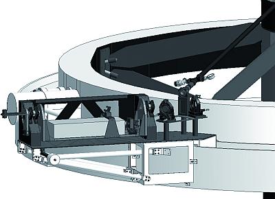
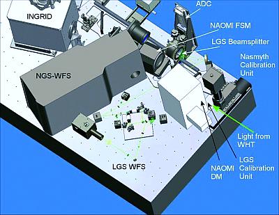
The GLAS cradle (top-end ring) and the layout of the optics on the
GRACE optical bench are shown below (also taken from
the newsletter article):
Individual components in the GLAS launch system:
- IR pump laser, housed in the GRACE electronics room.
- GLAS laser (5149 A), mounted in a cradle on the WHT top-end ring.
- Beam diagnostics
- Beam-launch telescope (BLT) mounted behind the secondary mirror.
The beam is 35 cm wide when it leaves the BLT, and focuses to a spot
10 cm wide at altitude 15 km (i.e. subtended angle ~ 1 arcsec).
The laser pulses at 5000 HZ?, and each pulse lasts 400 nsec?,
total power ~ 17 - 19 W, yielding an
artificial star with equivalent mag ~ 9.5?
Individual components in the GLAS LGS WFS light path:
- The beam-splitter (notch filter, 5149 A +- 75 A)
reflects returning laser light to
the LGS WFS arm, and passes the remaining wavelengths
(throughput 95%?) to the NGS / science camera.
The loss of wavelengths around that of the laser
affects the OASIS LR610, MR516, HR502 and HR530 configurations.
The filter is on a kinematic mount, and hence removable
(daytime job?).
- Field stop and 8-arcsec (pinhole) camera view (useful when steering laser
spot onto the LGS WFS).
- Laser steering mirror (LSM).
- Pockels cell (range-gate) shutter - determines the altitude (and duration) of the LGS light passed to the WFS.
- 4-arcsec (pinhole) inspection camera, just in front of LGS.
The surface is less reflective than that viewed by the 8-arcsec camera,
and the intensity of the light (range-gated) will be much less than
at the position of the 8-arcsec camera.
(NB the 4-arcsec camera before the LSM is not present.)
- Shack-Hartmann array.
- CCD
Useful numbers:
- Rotator centre on AG3 determined 24/8/07 to be at 594.5, 452.3.
- To focus a natural guide star (rather than the LGS)
on the LGS WFS, increase the WHT focus
by 7 mm. To focus on cloud, decrease the WHT focus by a few mm.
- Turbulence above La Palma - > 70% is from < 3 km (JKT scidar?).
GLAS control gui:
AO light-path mimic:
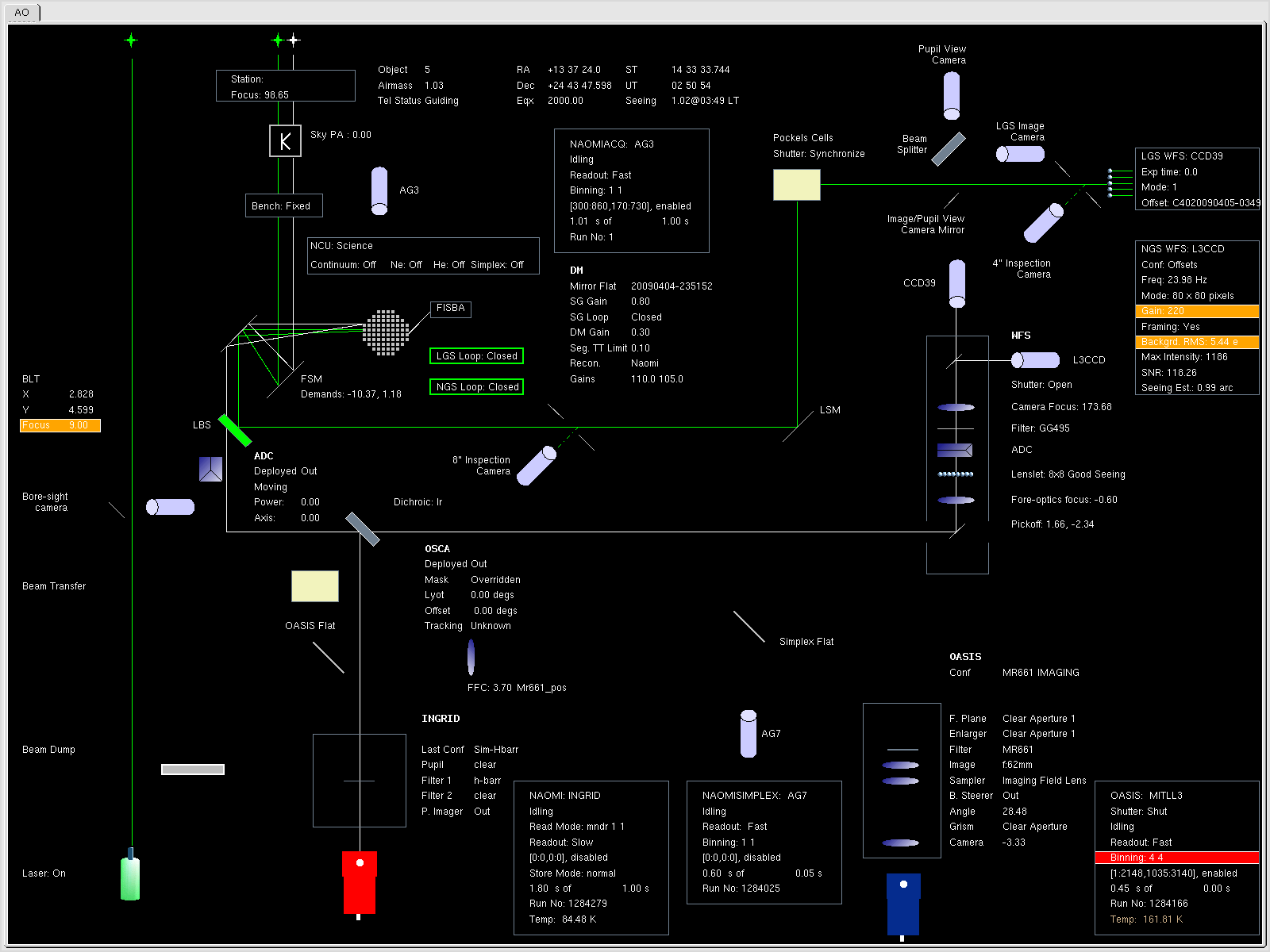 For a more recent version of the mimic,
taken with the laser
not firing and with OASIS in the light path, click here.
with
For a more recent version of the mimic,
taken with the laser
not firing and with OASIS in the light path, click here.
with
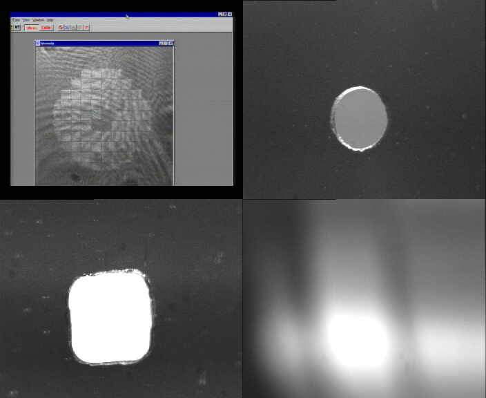
GLAS internal-camera images,
including (clockwise from top-left): DM, 8-arcsec inspection camera,
pupil-view camera, 4-arcsec inspection camera, as seen at night:
and with lights on in GRACE:
Top-end camera:
GLAS BLT camera images:
This section is a dumping ground for recipes for things that
might need doing occasionally, or that we used to have to do but
don't any more.
Check laser range and duration (not normally required)
The range (A) and duration (B - A) of the pulses / range-gating
should not be adjusted. For reference, the control is on the GLAS
rack in the electronic room in GRACE.
Use keys 2, 8 to increase or decrease the range.
Use the 'delay' key to switch between A and B.
More detailed instructions can be found in the email from Tibor (date??).
Check the laser alignment (not normally required)
- Determine the rotator center on any camera
- Put a bright star on the rotator center
- Defocus the WHT to bring the star in-focus on LGS-WFS;
this will
require ~ 7mm positive shift to the WHT focus
- Put the LSM at the mid-range values of 4096 in x and y
- Find the star in the WFS by
moving the telescope, center it up, and record the positional offset.
The importance of the telescope focus
requires some explanation.
The LGS-WFS has a fixed focus position
where the reference is the laser calibration source.
The laser
calibration source is conjugated to some fixed distance from the
telescope (typically, 15km).
That distance is defined by the timing
delay set for the Pockels cell shutter.
If the WHT focus is not at the
correct value then this will affect also the laser beacon focus and
hence introduce an unwanted focus term on the LGS-WFS.
The system will
want to take out this term by demanding the DM to correct for
it.
Whether there is a focus problem can be tested by checking the
focus demand from the LGS-WFS in open-loop and closed-loop mode.
There
should be no difference between the two situations.
To get readout of
the focus term, type PrintFocus 10.
The output is in (approximately)
the same scale of the WHT focus.
If there is a significant difference,
the WHT focus may be wrong, or the range-gate distance must be
adjusted.
Switching between LGS and NGS modes
*** As of 5/08, this section is probably superfluous.
Switch to NGS mode on sextans (for unknown reasons, this is essential
before switching to LGS mode):
- In an lpss42 xterm, login with su eladmin (password same as for naomi),
then ElectraKillAll, which kills all lpss42 windows.
- Click on the '8-bit sextans' icon to start an xterm on sextans.
Repeat, to start another.
(If you open any further xterms from these
windows, you need to type obssys in each of these, to make sure
the command-name aliases are set up.)
- In one of the sextans xterms, type 'GlasRestart'.
- In the other sextans xterm, type CameraSwitch.py, select 'master'
for the NGS camera.
- From the same window, type topgui & to bring up top gui.
- From the 'setup' tab on top gui, select NAOMI, for NGS mode.
- On the SDSU page of top gui, type re-init.
- Start framing, WFS frames should now be displayed.
Switch to LGS mode on sextans:
- On the CameraSwitch gui, switch to 'slave', for LGS.
Check that the status updates to slaveSynch on the GUI.
CameraSwitch.py tells the C40s which camera to read.
- Re-init SDSU. This may be needed several times.
If it proves stubborn, login to aocontrol1 as naomi, type WFS Start,
and WFS Status. If it it still won't start, power cycle
(see the NAOMI troubleshooting notes).
- Start WFS framing,
select continuous display.
- Change the NGS WFS camera stage focus to 172 from an epics control
window (start_epics?).
- From setup tab on top gui, select GLAS.
(Or TopGuiGlas & to force colour lookup table to be
correct - brings up small window 'medm'.
Several lines 'Checking...' will apppear, they should all end in 'OK'.
Both topgui and TopGuiGlas by default bring up top gui in LGS mode.)
- From real-time page, load reconstructor 'naomi',
gains should be 110 105.
(To switch to NGS mode, follow a similar procedure, but select NAOMI
(not ELECTRA) rather than GLAS, and select master
instead of slave.
The NGS WFS camera stage focus for the EEV39 (NGS high-order AO)
is 210.)
Depending on what's required, it may also be necessary to make
manual changes in GRACE:
- Below the lens on the front of the NGS WFS camera stage is a switch.
Slide it to the CCD39 position for NGS, CCD60 for LGS
(see the label on the top of the outer casing of the WFS).
Detailed instructions can be found
in
Jure's .pdf recipe for switching between modes.
|


