 | |||
|

| Home > Astronomy > AutoFib2 > Reflection/echelle modes |
|
| |||
|
| Home > Astronomy > AutoFib2 > Reflection/echelle modes |
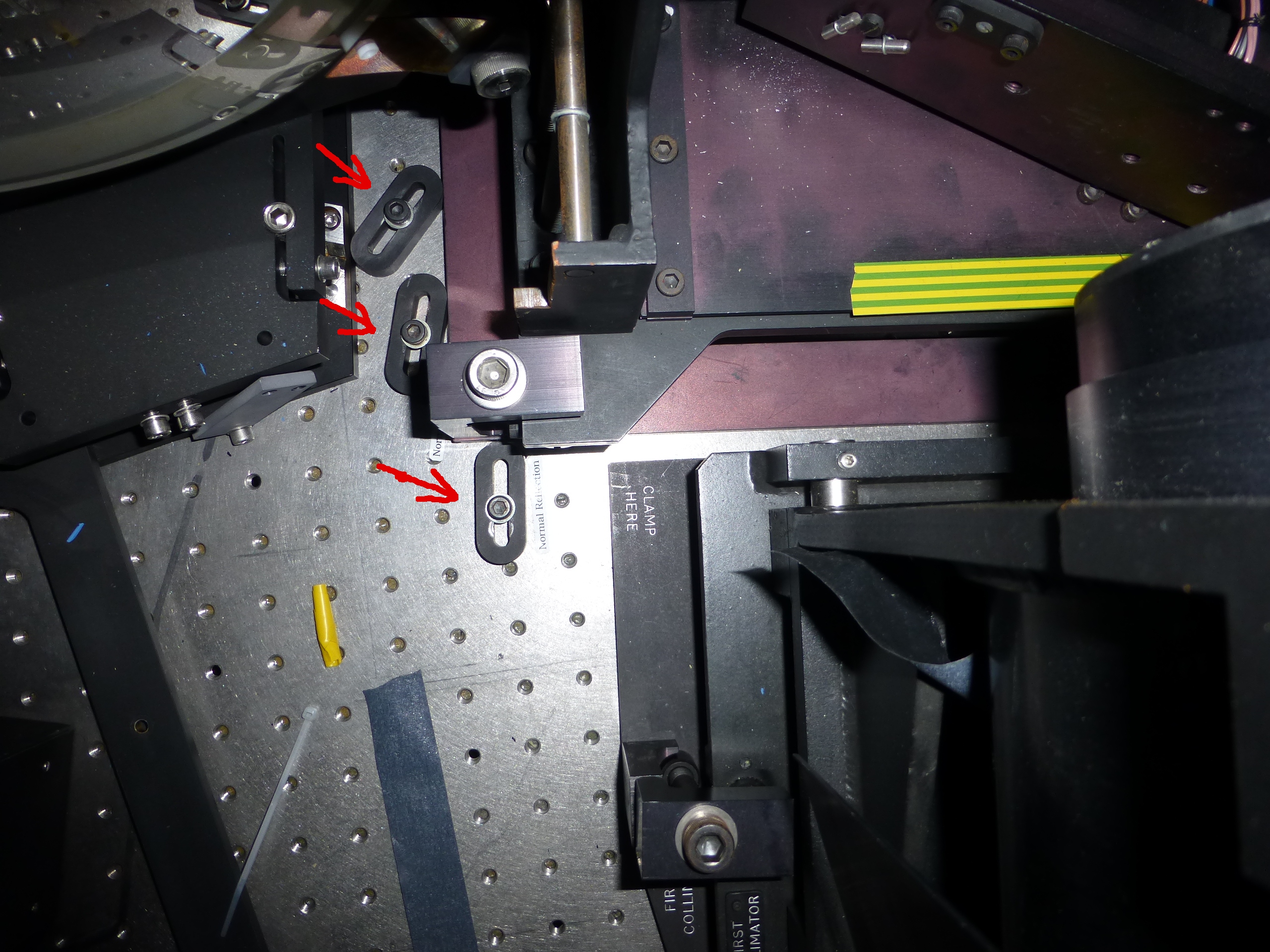
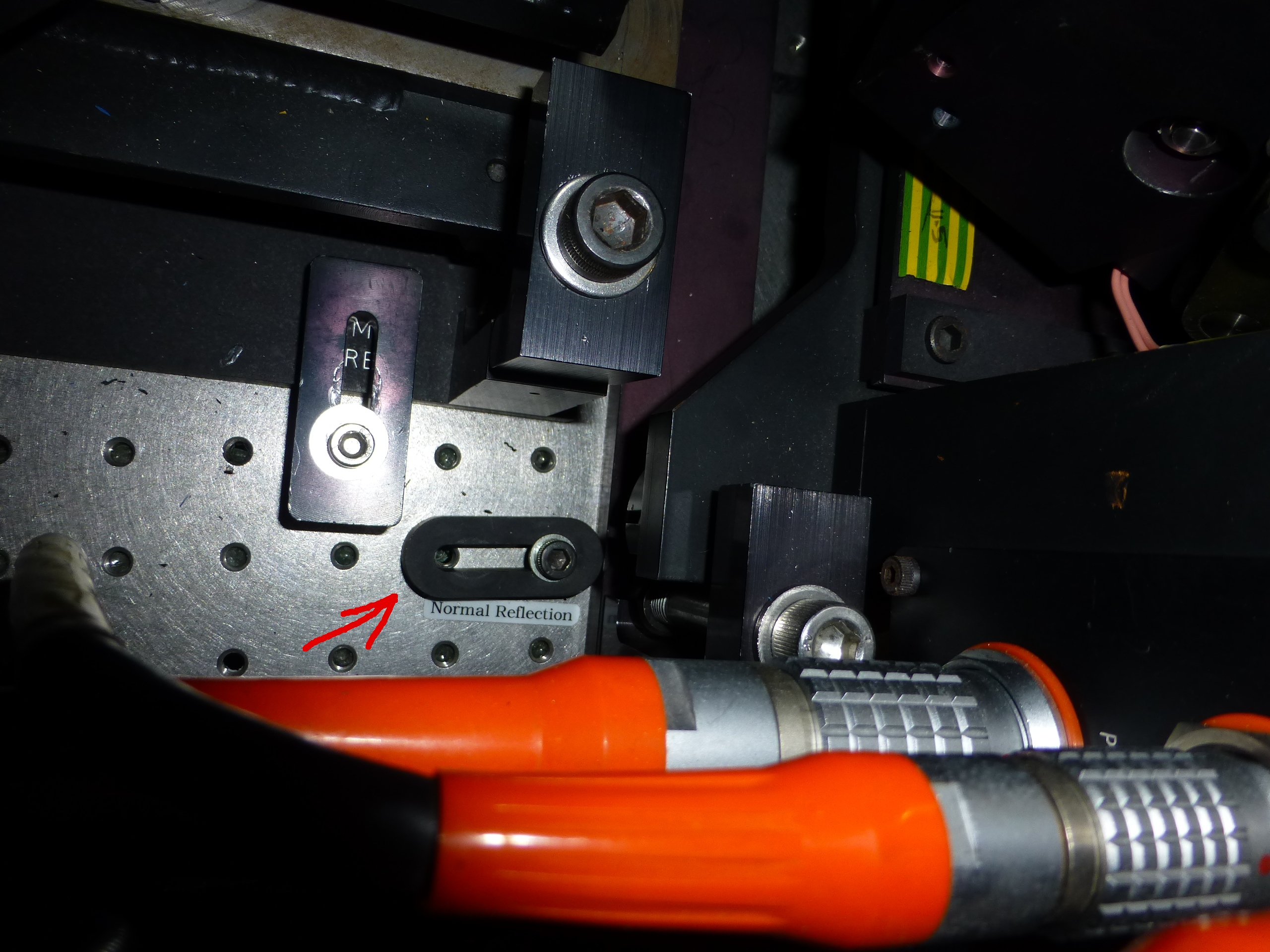
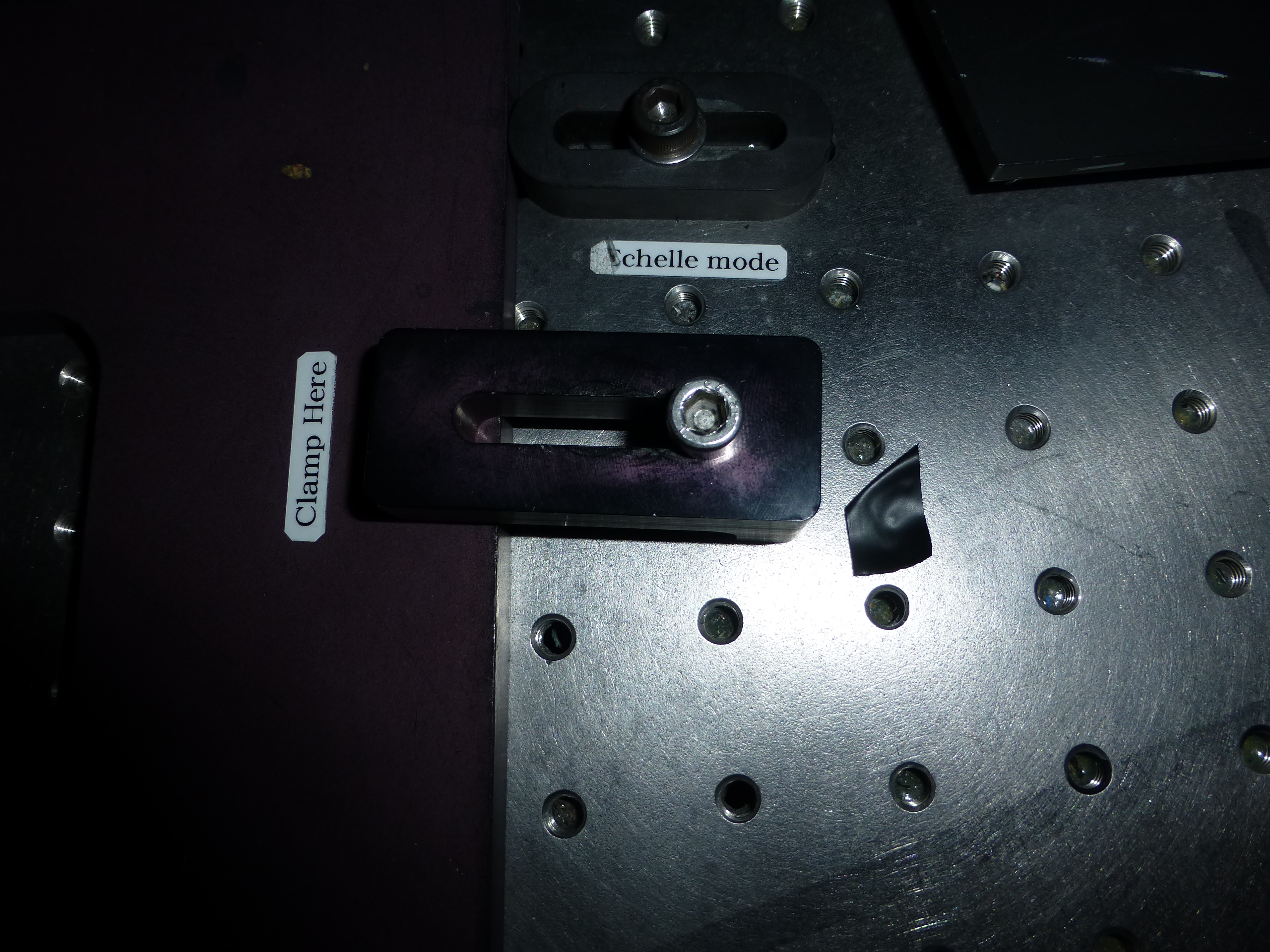
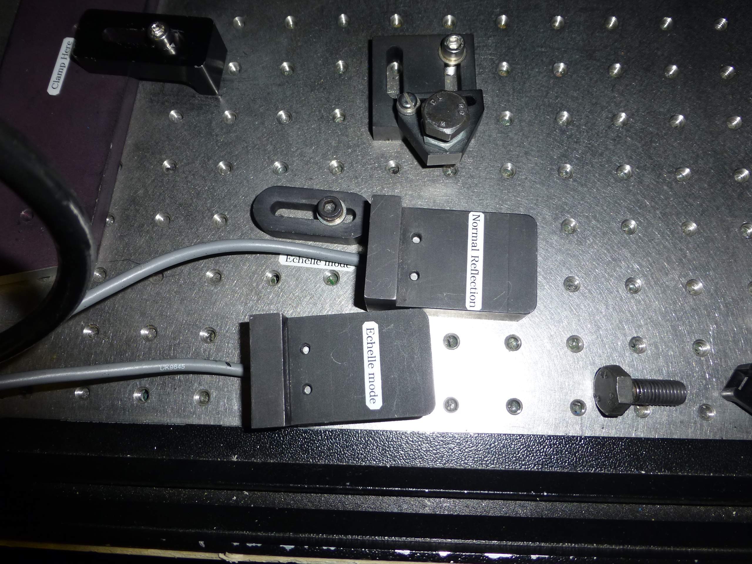
Changing between normal reflection and echelle modesTo change from normal reflection mode to echelle mode of operation requires the grating cell to be moved back 68 mm from its normal position (away from collimator) and 2 mm toward the access door.The normal reflection position is defined by 4 definers/stops. Two are positioned either side of the collimator, and the third and fourth ones are placed together on the side of the grating cell nearest to the camera. See Figure 1.
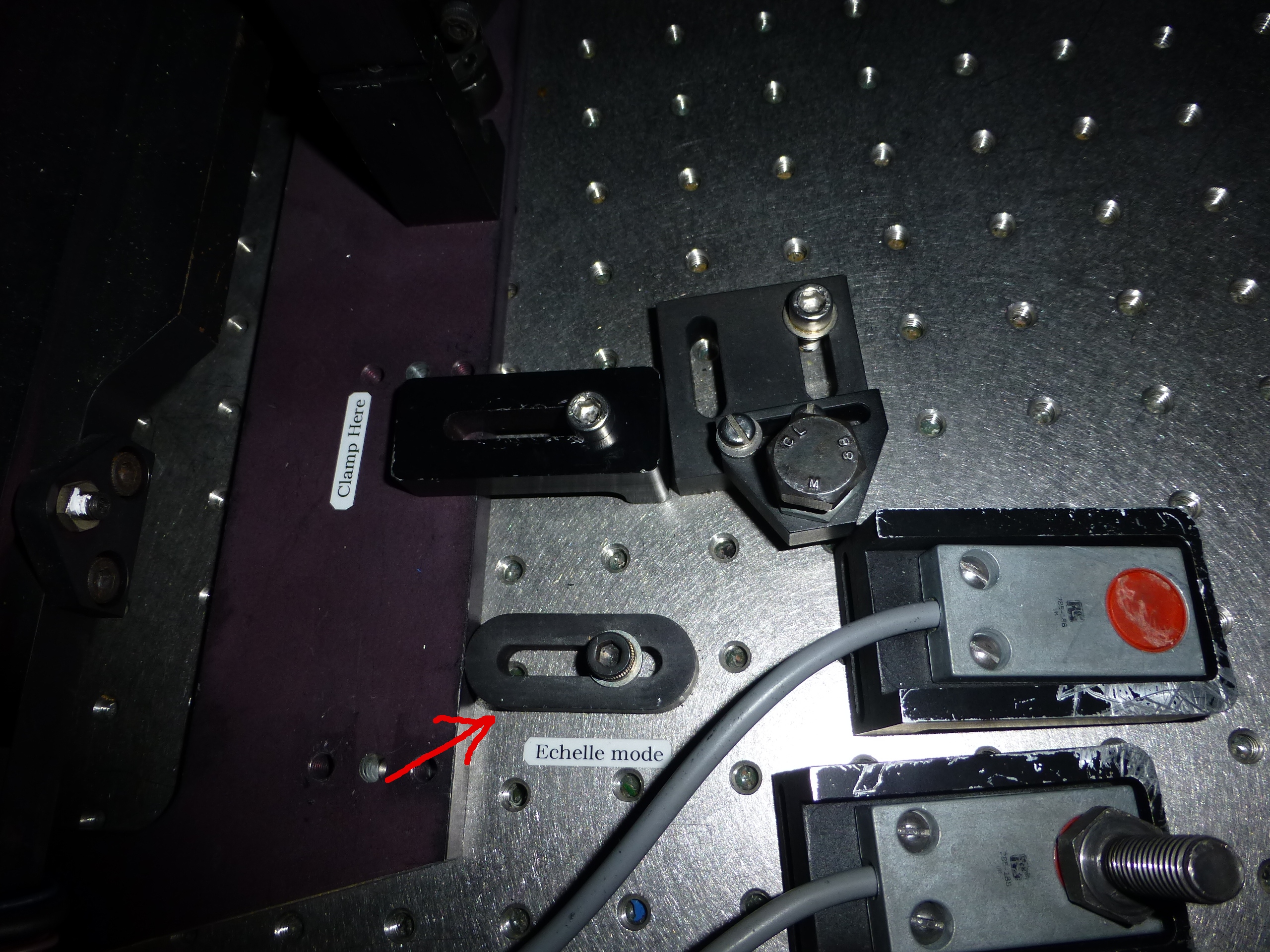
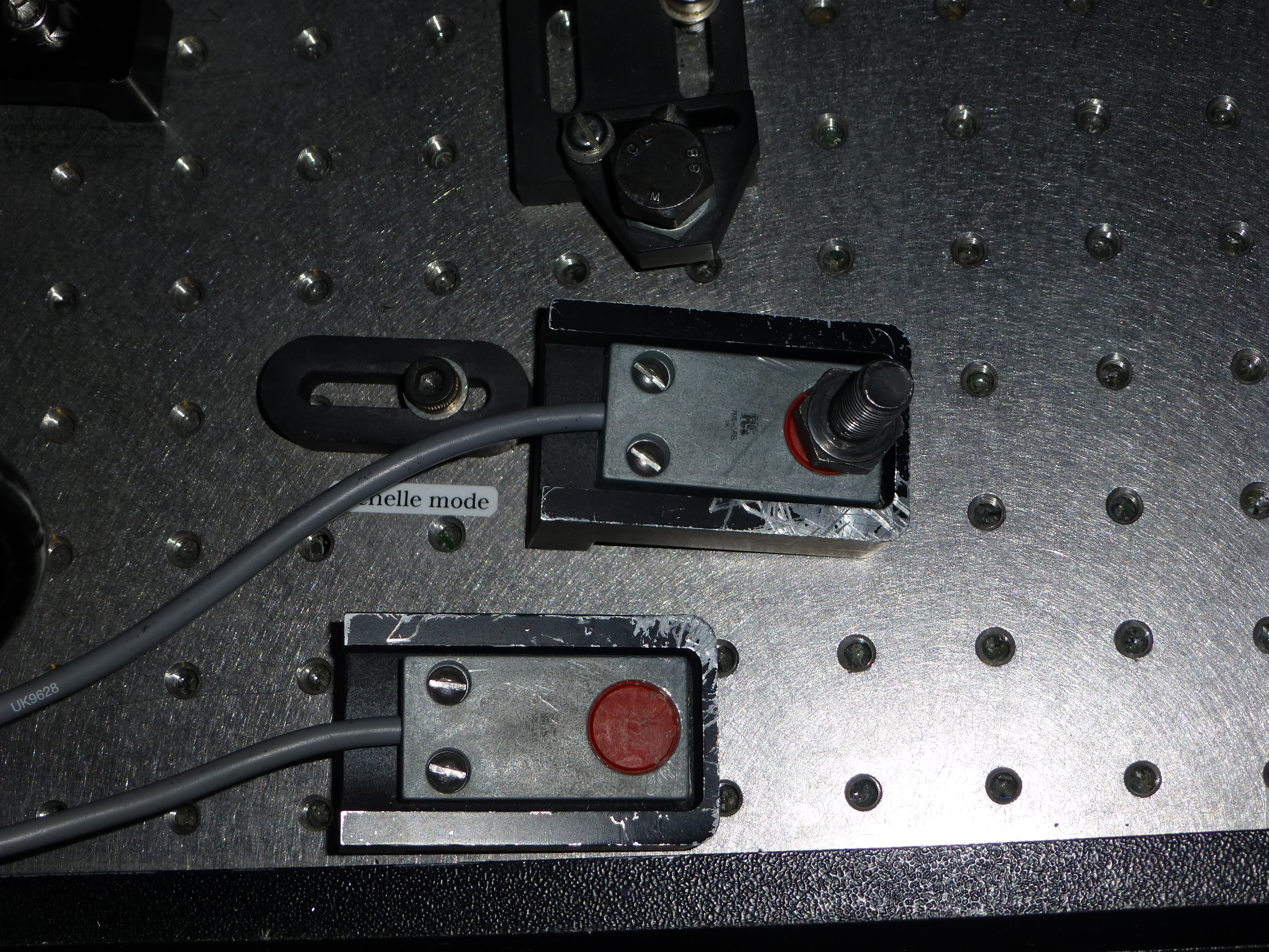
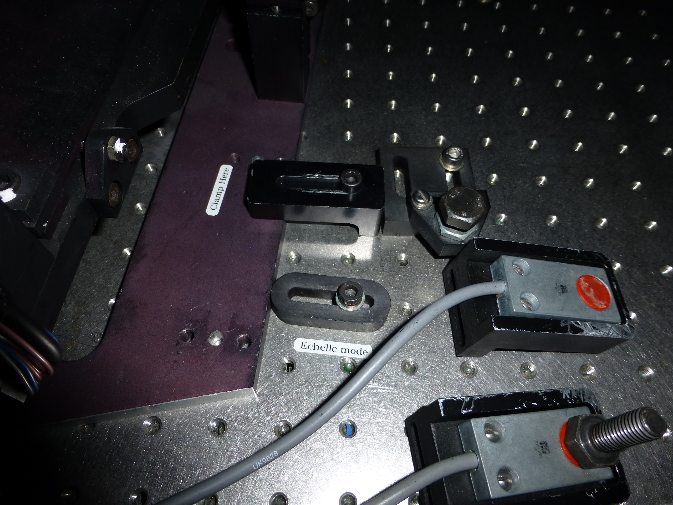
The echelle position is defined by 3 definers/stops; two of them are in both sides of the front of the grating cell, 68 mm from it in its normal reflection mode, the third one is on the side of the grating cell nearest to the camera, defining the position of the grating cell corner. See Figure 2.
Going from normal reflection to echelle
To go from the normal reflection to echelle mode follow the steps below: 1.- Remove the grating inside the cell. This is critical as the grating might be damaged if it is left inside while moving the cell. 2.- Remove the three clamping brackets holding the grating cell baseplate to the table. Two of them are along the front of the grating cell, there are two sticks marking the place where clamps should be. The third one is on the grating cell side closest to the access door. 3.- Pull the grating cell back and towards you until it comes into contact with the echelle mode definers, as in Figure 2. Check that the cell is really touching the three stops/definers. 4.- Clamp the baseplate to the optical table; two of the clamps go along the front of the grating cell, there are two sticks marking the place where clamps should be. The third clamp goes to the back of the grating cell, closer to the collimator. 5.- Mount the echelle grating in the grating cell. Check that the grating is well sitted. 6.- Place a bolt on the echelle mode switch (check the stick on the other side of the switch) to allow the system to recognize the echelle mode. 7.- Insert the required order-sortig filter at the filter position B, the closest one to the slit unit. Take into account that the filter in position A might vignette the light beam. Then update the filter database accordingly at http://whtics.roque.ing.iac.es:8081/FilterDatabase/. 8.- Update the new spectrograph setup at the WYFFOS mimic in the observing system: - Set the grating and the echelle order YY: SYS> wchange -grating echelle -offset 6.85 -order YY - Set the central wavelenght to XXXX: SYS> wcenwave XXXX YY (Note: it is very important to set the order again with this command, as it overrides the order set by "wchange") - Update filters in the left bottom corner button of the WYFFOS GUI - Put the sorting-order filter in the light path: SYS> wfilter B IN - Set spectrograph focus to zzzz nm. SYS> wsetfocus zzzz Check in the WYFFOS mimic that the grating name, the cenwave, the order and the focus are the right ones. 9.- Check the spectral range. - Switch on one of the arc calibration lamps and take an image. - Display the image on the ds9, overplot the fibres regions at /home/whtobs/AF2/ds9Reg/bin2red+4.reg and check that the fibres lay aproximatelly at the same position of the regions, no more than ~10 pixel shifted. - With imexam, do a vertical cut (with c) and check that the arc lines correspond to the expected spectral range. 10.- If the spectral range or the fibre position, with respect to the regions, are very shifted, check that the grating is well sitted in the grating cell, and that the grating cell is well placed in the positions defined by the stops described above. Going from echelle to normal reflection
To go from the echelle to the normal reflection mode follow the steps below: 1.- Remove the echelle grating inside the cell. This is critical as the grating might be damaged if it is left inside while moving the cell. 2.- Remove the three clamping brackets holding the grating cell baseplate to the table. Two of them are along the front of the grating cell, there are two sticks marking the place where clamps should be. The third one is on the back of the grating cell closest to the collimator. 3.- Pull the grating cell back until it comes into contact with the reflection mode definers, as in Figure 1. Check that the grating cell is really touching the four stops/definers. It is particularly difficult to check some of the stops as they are not visible from the access door, hence try taking a picture or using a small mirror. If the cell is not touching these stops, the spectral range and/or the position of the fibres on the CCD might be shifted. 4.- Clamp the baseplate to the optical table; two of the clamps go along the front of the grating cell, there are two sticks marking the place where clamps should be. The third one goes to the side of the grating cell closest to the access door. 5.- Mount the grating in the grating cell. Check that the grating is well sitted. 6.- Place a bolt on the normal reflection mode switch (check the stick on the other side of the switch) to allow the system to recognize the reflection mode. 7.- If any blocking filter is required, insert it at the filter position B, the closest one to the slit unit. Take into account that the filter in position A might vignette the light beam. Then update the filter database accordingly at http://whtics.roque.ing.iac.es:8081/FilterDatabase/. 8.- Update the new spectrograph setup at the WYFFOS mimic in the observing system: - Set the grating RxxxB: SYS> wchange -grating RxxxB -offset 6.85 -order 1 - Set the central wavelenght to XXXX: SYS> wcenwave XXXX 1 - Update filters in the left bottom corner button of the WYFFOS GUI - Remove the echelle filter from the light path (in case is needed put the filter required for the reflection mode in): SYS> wfilter B OUT - Set spectrograph focus to zzzz nm. SYS> wsetfocus zzzz Check in the WYFFOS mimic that the grating name, the cenwave, the order and the focus are the right ones. 9.- Check the spectral range. - Switch on one of the arc calibration lamps and take an image. - Display the image on the ds9, overplot the fibres regions at /home/whtobs/AF2/ds9Reg/bin2red+4.reg and check that the fibres lay aproximatelly at the same position of the regions (no more than ~5 pixels shifted). - With imexam, do a vertical cut (with c) and check that the arc lines correspond to the expected spectral range. 10.- If the spectral range or the fibres with respect to the regions are very shifted, check the grating is well sitted in the grating cell, and that the grating cell is well placed in the positions defined by the stops described above. |
| Top | Back |
|

