 | |||
|

| Home > Public Information > William Herschel Telescope > Mirror Support System |
The Primary Mirror Support Systems
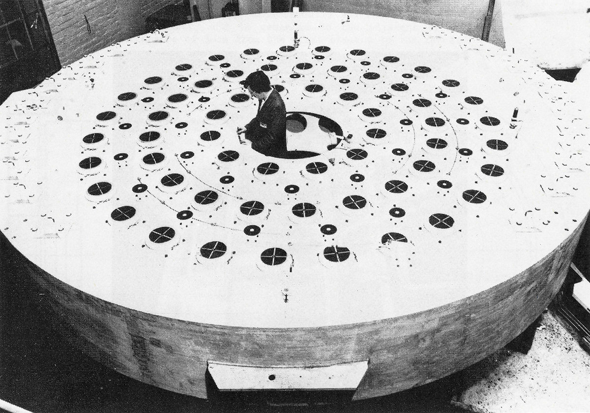
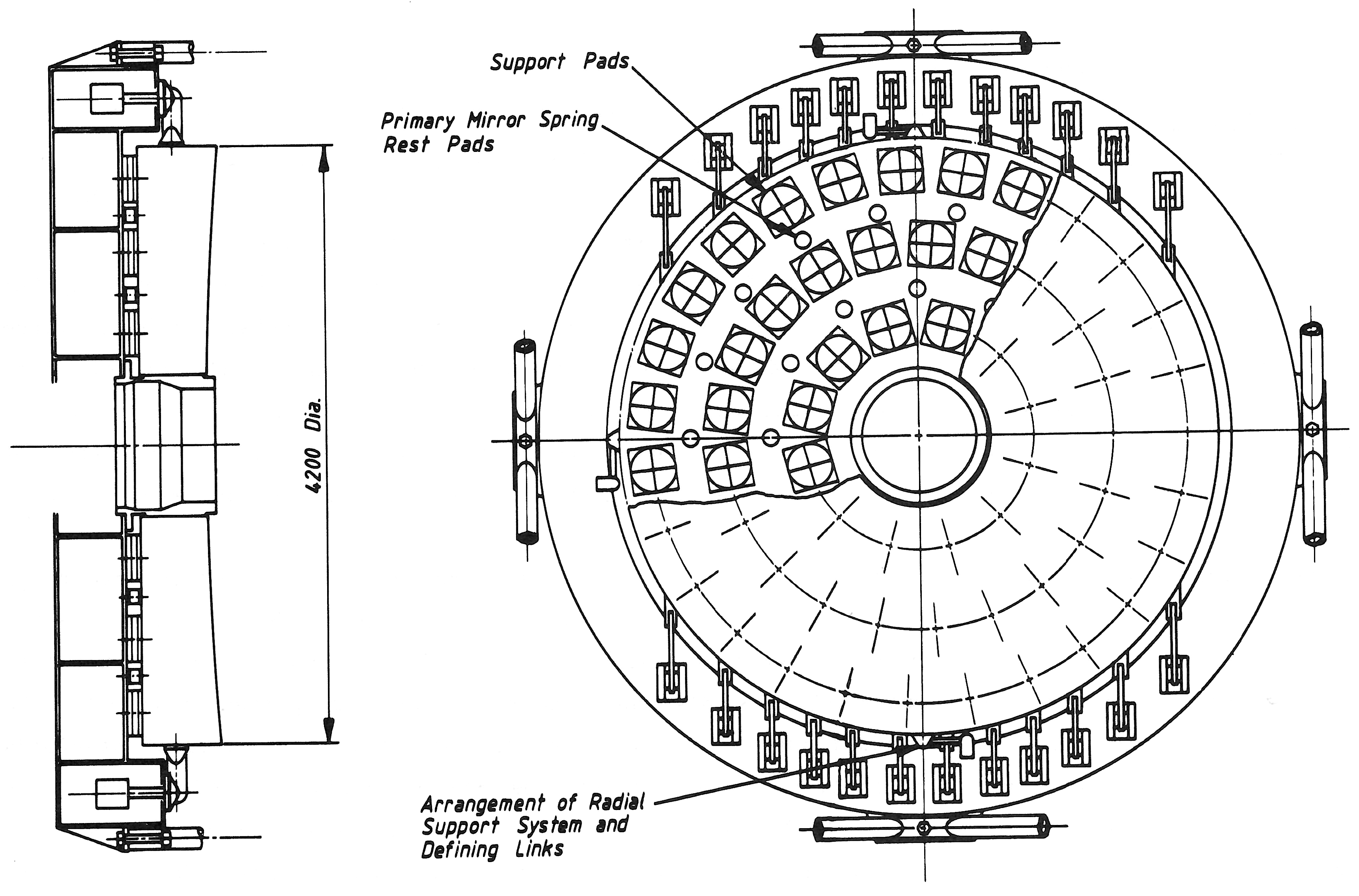
The primary mirror of the WHT has sophisticated axial and transverse support systems. The axial support system consists of two subsystems: an axial flotation system made up of an array of pneumatic cylinders ('belloframes') employing roll-diaphragms as seals, together with a pumping system providing the gas pressure needed to support the full mirror weight; and an axial defining system which locates the mirror in its correct position at three points around the mirror edge ('load cells'). Load sensors in the axial definers provide signals which control the pressure in the pneumatic cylinders; the system also allows fine height and tilt adjustments to be made. A system of spring-loaded rest pads supports the mirror when the pneumatic system is not pressurized. The cylinders of the axial flotation system, a total of 60, are arranged in concentric rings on the floor of the mirror cell. The optimum arrangement was determined by use of a finite-element computer analysis of mirror deflections. The cylinders are divided into three sectors each of 120 degrees, symmetrically disposed about a diameter perpendicular to the telescope's altitude axis. All the cylinders in each group are connected by a system of manifolds and pipes to an individual controller housed inside the mirror cell. Each of the three controllers have two sets of electrically-operated valves: one connects the cylinders to a pressurized nitrogen reservoir, the other opens the cylinders to a vacuum tank. The valves are controlled by the output of the associated load cell in such a way that the force exerted by the mirror on the defining point is maintained at 0±5 kg during tracking at all angles of the telescope tube from the zenith down to the horizon. The total weight of the primary mirror is 16.5 tonnes. This axial system is a servo one. The mirror is supported in a transverse
direction by mechanical weighted levers coupled by link arms to brackets connected
to the edge of the mirror ('axial definers') in much the same way as a conventional push-pull
radial support system. However, as the mirror will not rotate with respect
to the gravity direction, the weighted levers and linkages are arranged
to act only in the vertical direction and are spaced unequally in such
a way that each pair of weighted levers, one pushing and the other pulling,
effectively supports a 'slice' of the mirror equal to 1/2 of its total
weight. This efficient arrangement is only possible in an altazimuth
mounting. In plane view the force applied by each pair of weighted lever
acts through the centre of gravity of its slice, but in elevation all
the forces are applied in the one plane containing the centre of gravity
of the whole mirror.
Finally transverse (or radial) definers take the form of tangential
links tying the mirror to its cell at three 90 degrees positions.
 The 4.2m mirror cell and support systems showing tge array of pneumatic cylinders with (smaller) spring loaded rest pads. Extracted from A. Boksenberg, 1985, The William Herschel Telescope, Vistas in Astronomy, 28, 535 [ Larger size ].
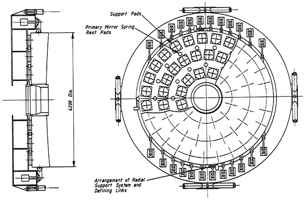 Primary mirror cell showing the axial and transverse support systems. Extracted from A. Boksenberg, 1985, The William Herschel Telescope, Vistas in Astronomy, 28, 535 [ Larger size ]. |
| Top | Back |
|
