| UK Astronomy Technology Centre | Chris Tierney |
| Royal Observatory, Edinburgh | 31st March 2001 |

The pickoff assembly is the collection of the more important, and inter-dependent, components of the wavefront sensor. It comprises five stages, each driven by a steppermotor:
Details of the inter-dependencies of these stages are given below in the section Parameter input/output.
Safety
All the NAOMI mechanism control screens display two buttons - a red "Emergency" button
and a green "Safe" button - in the top right corner of the screen.
Left clicking an "Emergency" button will immediately stop any motion by any part of the wavefront sensor or calibration unit. Thereafter, any demands for motion are rejected, until the user left clicks on any of the "Safe" buttons. Many mechanisms will then demand to be re-indexed before allowing the execution of any other motions.
Note: This safety feature has no effect on the motion of the Durham deformable mirror (DM) or fast beam-steering mirror (FSM), nor any component of the electronics associated with NAOMI.
For more information, see the NAOMI mechanism software
safety page.
Commands to the pickoff assembly
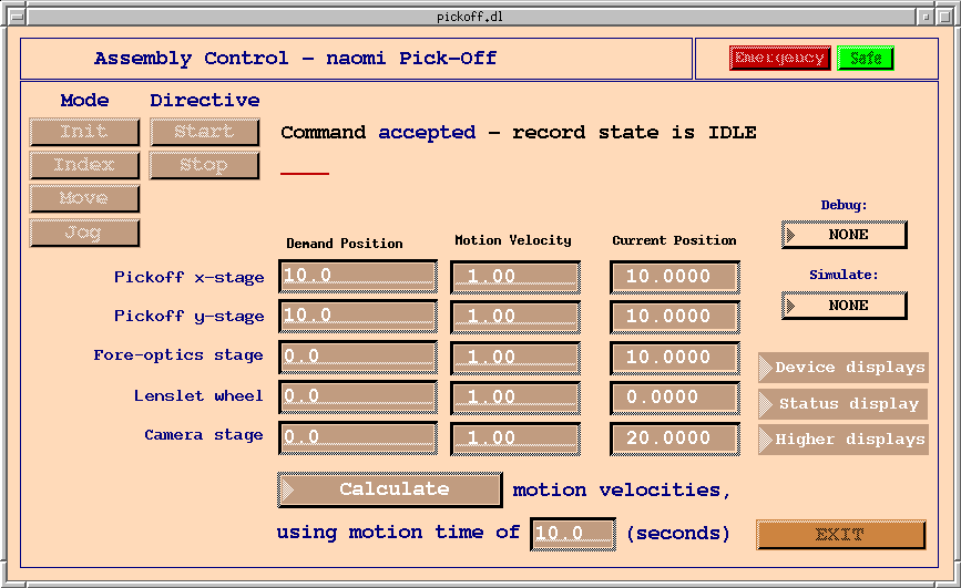
Before any operations are performed on this assembly, it must be initialised by left-cicking
the Mode button "Init", followed by Directive "Start". The user should see the status
display "Command accepted - record state is busy". The record state will return to
"idle" when initialisation is complete.
For all commands, in normal operation the user should see the status display "Command accepted - record state is busy" when the command starts. When the command is complete, the record state should change to "idle".
A status of "Command rejected" indicates that the command was not started. A status of "record state is error" indicates that the command did not complete succesfully. In both cases an error message will indicate the cause of the failure.
After initialisation, the mechanism should be indexed. This is started by clicking the "Index" Mode followed by "Start" Directive. The assembly then embarks on a somewhat complicated procedure designed to ensure that, no matter what the current configuration of the instrument, the five stages are able to index to their correct locations. These locations are:
The interested reader is advised to examine the NAOMI hardware to discover why such a convoluted procedure is required.
After index operation has been performed, the assembly is now available for normal use. The user should left-click the "Move" Mode button. Thereafter, clicking the "Start" Directive button will cause the assembly to move the pickoff stages to their specified locations. The assembly attempts, through the use of named positions, to maintain focus at the CCD cameras as the pickoff mirror is moved, or the lenslet selection altered (see below).
The "Stop" Directive button can be clicked at any time to bring the assembly to a controlled stop.
Parameter input/output
The five "Demand Position" input fields are provided for the user to configure the assembly. Input to the four linear stages
is in mm, with the lenslet wheel positions in degrees. "Demand Velocity" fields can also be modified by the user, although the
assembly will attempt to calculate appropriate velocities if allowed to do so. The following values should be used as the
demand positions for each device:
The net result of this calculation is that, provided the camera stage demand position correctly reflects the focal length of the selected lenslet and the fore-optics stage demand position is input as zero, the CCD cameras should maintain good focus on the guide star image whilst the pickoff mirror is moved across its field-of-view.
"Motion Velocity" input fields are provided for the user to specify the required motion velocity for each device. The user can leave these at their default (post-index) values if desired, or modify them within the velocity limits of each device.
For the user to specify each velocity in this way, the selector menu at the bottom of the screen should instruct the assembly "Do not calculate motion velocities, using...". Right-click and hold to modify this selector if required.
If the user changes the selector menu to "Calculate motion velocities, using..." the assembly will fill the velocity fields, before every move, with the values required for all five devices to complete their motions in the time specified. This can be helpful if the user requires the wavefront sensor to maintain focus during a long move of the pickoff, but requires careful selection of the motion time if the derived motion velocities are to remain within allowed limits.
The "Current Position" indicator fields display the eventual position, from the index location, for each device in the assembly.
The specifications of these named positions, along with values for the offsets used by the assembly (see above), are determined by the software during initialisation using the pickoff assembly lookup table. Details of the lookup tables used by the NAOMI mechanism control software are available on the NAOMI mechanism control software lookup tables page included in this documentation. We describe the named positions for the pickoff assembly in more detail here.
At the time of this writing, the defined "named position" string are as follows:
In normal use, however, the string "focussed" should be used. This causes the assembly to select the correct focal length, based on the (valid) named position contained in the lenslet wheel demand position field.
Two further names are provided for engineering purposes: "pupil" has the numerical equivalent 0.0 and "near_pupil" has the equivalent 10.0. They are used to place the camera stage at (or near) the pupil focus of the wavefront sensor.
Menu items
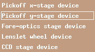
Five items are provided in the Device displays menu - to access the deviceControl screens for each of the
pickoff assembly devices.

Status and Higher displays menus give access to further assembly information and the top-level screens, respectively.