| UK Astronomy Technology Centre | Chris Tierney |
| Royal Observatory, Edinburgh | 31st March 2001 |
The NCU calibration lamp consists of a source lamp which illuminates an integrating sphere through a variable (controllable) aperture. Rotation of this aperture is achieved using a steppermotor. A photodiode is intalled within the sphere to monitor light intensity. A pinhole in the sphere provides the point source that is used as the calibration source for NAOMI.
After calibration of the software, the user is required to specify the illumination that is required within the integrating sphere, although a scaling factor (not currently used) has been provided to enable this input to reflect the point source illumination that results, if required.
Upon receiving the request to "Hunt", the software proceeds to rotate the aperture whilst
monitoring the photodiode output. The software will continue in this way until the measured
photodiode output is within an acceptable range of the value requested.
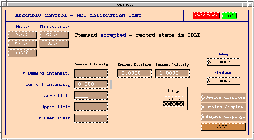
Safety
All the NAOMI mechanism control screens display two buttons - a red "Emergency" button
and a green "Safe" button - in the top right corner of the screen.
Left clicking an "Emergency" button will immediately stop any motion by any part of the wavefront sensor or calibration unit. Thereafter, any demands for motion are rejected, until the user left clicks on any of the "Safe" buttons. Many mechanisms will then demand to be re-indexed before allowing the execution of any other motions.
Note: This safety feature has no effect on the motion of the Durham deformable mirror (DM) or fast beam-steering mirror (FSM), nor any component of the electronics associated with NAOMI.
For more information, see the NAOMI mechanism software
safety page.
Commands to the NCU lamp assembly
Before any operations are performed on this assembly, it must be initialised by left-cicking
the Mode button "Init", followed by Directive "Start". The user should see the status
display "Command accepted - record state is busy". The record state will return to
"idle" when initialisation is complete.
For all commands, in normal operation the user should see the status display "Command accepted - record state is busy" when the command starts. When the command is complete, the record state should change to "idle".
A status of "Command rejected" indicates that the command was not started. A status of "record state is error" indicates that the command did not complete succesfully. In both cases an error message will indicate the cause of the failure.
After initialisation, the mechanism should be indexed. This is started by clicking the "Index" Mode followed by "Start" Directive. Index mode for this assembly differs from that of other assemblies because there are no home or limit switches installed on the aperture mechanism. The assembly simulates an index by rotating the aperture mechanism through (more than) one full revolution, periodically recording photodiode readings throughout the motion. The aperture angle at which the lowest illumination was recorded is considered to be the lower limit for the stage. Similarly, the highest illumination is recorded as an upper limit. At the end of the index process, the stage is moved to its new (derived) lower limit.
After these operations have been performed, the assembly is now available for normal use. The user should left-click the "Hunt" Mode button. Thereafter, clicking the "Start" Directive button will cause the assembly to start rotating the aperture mechanism, seeking the illumination demanded by the user (see below).
The "Stop" Directive button can be clicked at any time to bring the assembly to a controlled stop.
Parameter input/output
The parameter i/o section of the screen contains several control and indicator fields. Simplest of these is the "Lamp
enabled/disabled" selector button. The user is required to enable (switch on) the lamp before executing the "Index"
or "Hunt" modes. The screenshot above shows the lamp disabled.
The "Lower limit" and "Upper limit" indicators are updated by the software after an index operation. These are the minimum and maximum photodiode readings recorded during the indexing process and are, therefore, the allowed range of illumination that can be selected by the user during a "Hunt" operation. "User limit" is provided for the user to manually specify an upper limit for illumination in order, for example, to avoid damage to some component of the wavefront sensor downstream of the calibration source.
The important input field on the screen is "Demand Intensity". The user should enter a value (between the upper and lower limits) in this field before starting a hunt operation. The screen will continually update, showing the "Current (measured) intensity" from the photodiode, "Current (anguler) position" of the aperture (degrees) and "Current (angular) velocity" (degree/sec), until the hunt operation completes.
This assembly implements a simple (go higher or go lower?) algorithm to seek the requested intensity, and the user will notice the "Current velocity" field being updated as the software attempts to home in on the correct orientation for the aperture mechanism.
Menu items
Only one item is provided in the Device displays menu - to access the deviceControl screen for the
Lamp attenuator (aperture) device.

Status and Higher displays menus give access to further assembly information and the top-level screens, respectively.