|
|
Mechanical Engineering Group
Specifications |

This section contains details of the system and its components as it is currently in use.
The system consists of the following parts:
- Compressor
- 50 to 60 Hz converter
- Coldhead
- Helium flexlines
Apart from this there's other parts that are used to do maintenance on the system:
- Maintenance manifold
- Heliumheater
- Coldtrap
- Vacuumport
Compressor:
|
 |
| Static pressure | Amps @ 208V | Range AC voltage | Coldhead voltage | Total power |
| 250 Psi | 10 A | 198-250V | 138-162V | 2.1Kw |
The compressor has four functions:
- It compresses the Helium
- It cools the oil, used to carry the heat of compression out of the compressor
- It removes any remaining oil in the helium stream
- It supplies the coldhead with power
Adsorber:
| S/N8080255K001 |
|
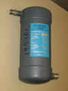
This is fitted into the compressor. It is a sealed container filled with activated charcoal inline with the rest of the system. It removes what little oil remains in the helium by adsorption. Like a cryopump it's a capturing device and it must be periodically be replaced as it will fill up. The 8200 compressor needs an adsorber change each year.
50 to 60 Hz converter:
This convertor is used to change frequency from 50 to 60 Hz. The system will work slightly better when operated at 60 Hz.
Coldhead:
| M-1050 CP Single stage coldhead.
S/N15A0113598 model 8004502
|
 |
The coldhead consists of the coldhead cylinder and the displacer assembly. These together produce close-cycle refrigeration. During operation, high pressure helium from the compressor enters the coldhead and flows though the displacer before leaving at the return-connector. In the displacer-regenerator assembly helium expansion takes place and provides cooling.
Helium flexlines.
| 1/2" ID straight 20 feet. |
These lines connect the coldhead to the compressor. Each flexline is sealed by two aeroquip self sealing connectors on each end. The lines are filled with pure helium and therefore can be connected to the system immediately.
Maintenance manifold.
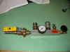 |
The maintenance manifold is used to add helium gas to the flexlines and the coldhead. The heliumheater can be mounted on it aswell and that way the purge gas can be heated. The manifold has two 1/2" aeroquip-connectors (male/female), 1/4" aeroquip-connector (male), 1/8BSP nipple to connect the helium fill line. Further a manometer and a ball valve are fitted aswell.
Heliumheater:
| P/N 8080250K020 | 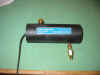 |
This piece of equipment is used during regeneration of the system. With time the components which contain activated charcoal, will collect contaminants. Therefore from time to time these parts have to be 'cleaned'. If the charcoal is heated up it will be easier for the molecules to leave the walls in the adsorber and can be extracted from the system.
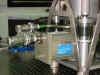
Coldtrap:
| serial number | 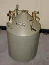 |
The coldtrap is used to collect contaminants from the system. The coldtrap consists of a tank that is filled with liquid LN2. Through different pipes and valves the helium is fed through it. This way all contaminants will freeze in it and be removed from the system. This again, is a capturing device and therefore it has to be regenerated from time to time aswell. It is used to clean the compressor when contamination is suspected. It can be used to clean the whole system except the coldhead (contaminants will freeze in the coldhead which will be colder). If pure helium gas is needed to top up the system the coldtrap can be used to clean the purge gas before it enters the system.
Vacuumport:
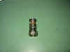 |
The vacuumport consists of a standard balzers vacuumflange welded to an aeroquip connector. With this it is possible to pump the heliumlines. This can be useful to test the system for leaks and for cleaning purposes. When pumping a system that is possibly contaminated you should be careful using vacuum pumps. The pump will get rid of water vapour, but oil and other contaminants will do damage to the pump. Therefore it is suggested that you use the coldtrap.
Last Updated 07/06/2002, Michiel van der Hoeven