
assemblyControl Record Reference Manual

This document describes the assemblyControl record created by the Herzberg Institute of Astrophysics.

This document describes the assemblyControl record created by the Herzberg Institute of Astrophysics team for integrated control of the deviceControl record See deviceControl Record Reference Manual (deviceControl/01), William Rambold that controls DC and Stepper Motors. This design is expected to evolve as the development of the record proceeds.
This document defines the interface to the assemblyControl record only. For a list of EPICS records created by and for the GEMINI project see the Gemini Record Reference Manual See Gemini Record Reference Manual (spe-c-g0070/02), Bret Goodrich and Andy Foster. For a complete list of the standard EPICS records, and a description of the field summary tables, refer to the EPICS Input Output Controller Record Reference Manual See EPICS Input Output Controller Record Reference Manual, Janet B. Anderson and Martin R. Kraimer, Argonne National Laboratory, Dec 1, 1994..
Following are some broad definitions of concepts used throughout this manual:
Assembly: An assembly is a collection of devices that must work together to perform a specific instrument function. The assemblyControl record abstracts the actual details of assembly operation from higher level control layers. The record support level interactions are standard for all assemblyControl records while the details of assembly operation are implemented in a custom device support layer.
Device: A single moving component in an assembly. It is controlled by a deviceControl record.

The section to follow is a record overview which includes a field summary for the record and configuration instructions for the record. The next section will detail the operation of the record. Next are the typical scenario's of the a record and finally details of the support modules that make up this record.

An assembly provides a method of coordinating the actions of one or more devices in a synchronous or asynchronous manner. The devices are controlled and represented by the deviceControl record, and the assembly will be controlled and represented via the assemblyControl record. This document describes the design of the assemblyControl record.
The assemblyControl record communicates directly with the deviceControl record(s) via custom device support and at the database level. The deviceControl record is defined in See deviceControl Record Reference Manual (deviceControl/01), William Rambold.
For any record type there are record and device support modules. The record support module will handle all record specific details that are common for all assemblies. The device support module must be configured for the needs of each individual assembly.
General features of the assemblyControl record include:
Any errors detected in the above will generate a diagnostic message explaining what happened.

|

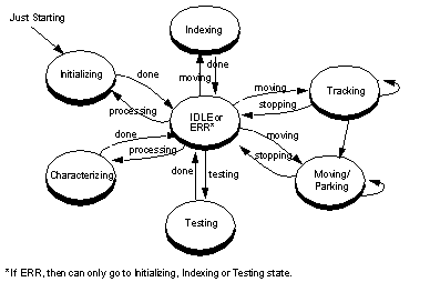
See Assembly Control Record shows the assemblyControl record fields available from a configuration tool (e.g. CAPFAST). See assemblyControl Record States is a diagram of possible states that the assemblyControl record can enter.
|
See assemblyControl Record Field Summary is a summary of fields for the record instance. All of these fields, plus additional standard fields (see See Additional Standard Record Fields) defines the record structure that is accessed via the module code. The field, brief description and type are included. Column 4 (DCT) indicates if the field will appear in a configuration tool, column 6 (Access) indicates if the field can be read, column 7 (Modify) indicates if a field can be written to, column 8 (Rec Proc Monitor) indicates if the field can raise a monitor, and column 9 (PP) indicates that changes to the field cause the record to be processed if set to Yes.
A few notes about some of the fields:
Each assemblyControl record must have device support code written for it. The functions that need to be written are shown in See Function List under "Device Support Module Function List.". Each assembly will have different functions and needs. For example, an assemblyControl record may be controlling 2 motors (via the deviceControl record), that can act independently, which means they can both be told to move at the same time or sequentially with the second waiting for the first to complete. Configuration of the custom device support code is indicated through the `DTYP' field in the record.

assemblyControl record operation is controlled by the DIR and MODE and can use any and/or all of the input attribute fields (A-E) and input sensor fields (SIJ-SIN). In normal operation, attribute parameters are written to the appropriate fields and the START directive is issued to begin execution of the command. If a sequence involving more than one assembly is being prepared it will be possible to check the validity of the attribute information via the PRESET directive for all assemblies prior to starting the motions. If there are no changes in the attribute fields, then the MARK directive must be issued prior to any PRESET, START or STOP directive being issued. Any operation can be halted, at the next reasonable interrupt point, via the STOP directive. Though these attributes are interpreted, it is up to the custom assemblyControl code in the device support package to implement them. This section will discuss generally the DIR and MODE fields and their proposed functions.
Commands to the attached devices are sent via the DIR fieldSee ICD 1b The Baseline Attribute/Value Interface (gscg.grp.024/04), Kim Gillies, Steve Wampler, Bret Goodrich.. Possible values are STOP, MARK, CLEAR, PRESET and START. The following section details each. The general sequence of events are:
This directive terminates a command in progress. The record support routine simply calls the device support routine: stopDirective(). The following is a suggestion of what the device support should do.
The directive should be passed on to any attached devices which will be stopped in a controlled manner. (For example: Consider a case with multiple devices attached which are controlled asynchronously. If the devices are currently executing a "MOVE" command and 2 of the 5 have completed, then the remaining 3 would be sent to the STOP command. Once all 3 devices have set their BUS* field to IDLE or ERR, then the BUSY field will be set to IDLE.) The STOP directive should simply be acknowledged if the attached devices are not currently executing a command.
This directive indicates that, should the PRESET/START/STOP directive be issued, functions should be executed. If there is no change in attributes A-E, or the MARK directive has not be issued, then the PRESET/START/STOP directive will be ignored.
This directive validates all of the input attribute fields by calling the device support routine checkAttributes(). CheckAttributes() returns a success or failure which the record support code handles as follows:
This directive either starts a new command action or updates the control parameters for a command in progress. All input attribute fields are validated prior to executing the command (see See PRESET, See PRESET). If it is safe to proceed the record is set to BUSY and the control information is processed according to the MODE selected. The record will remain BUSY until either the command has completed or an error is encountered. A timer may be used to deal with the completion of each device and ultimately the entire command. A timeout is used to catch when a device has not completed within a specific time, which may indicate a problem with the device.
When a START directive has been received, the operating mode field is consulted to determine how to process the command.
Initialize the assemblyControl record. The record support routine will:
The device support routine, initMode(), should consists of:
The INIT command should be rejected if any device is currently in motion. That means a STOP directive should be issued prior to doing an INIT. Also, an INIT does not automatically perform an INDEX command.
The MOVE command calls for synchronous or asynchronous movement of the attached devices. A new MOVE command can be issued while a MOVE command is currently active. The PARK command is a specialized move command to a device dependant safe storage position. The record support routine will:
The device support routine called is moveMode(). The general sequence of events is:
Any command that involves moving of a device (MOVE, PARK, TRACK, INDEX, STOP) cannot be interrupted and have the simulation mode changed. For example, if currently performing a MOVE command, the assemblyControl record cannot be put into VSM simulate mode and then receive a STOP.
TRACK mode calls for devices to be powered up, unlocked, moved to a position and remain powered on. This mode is useful when the device must follow a series of target positions with the minimum delay. A new TRACK command can be issued while the device is still in motion and will be acted upon immediately. A track command is meant to be executed quickly and should involve no limit checking or translation of input attributes. The sequence of events is similar to MOVE and not repeated here. The device support routine called is trackMode().
In INDEX mode all devices are sent to find their home or reference point. The general sequence of events is essential the same as MOVE and will not be repeated here. The device support routine called is indexMode().

The following section describes typical scenarios and the sequence of events that occur to handle the events. All functions/routines are listed in See Function List and the record support entries are detailed in See Support Entry Tables. See Scenario's lists all scenario's shown in the remainder of this section. Each scenario will include a brief description and then show the sequence of events that will occur to process the events. Please note that the device support code is described is in a VERY general sense as this code will be unique for each instance of the assemblyControl record. Only typical examples are given.
|
Initialization of a single instance of the assemblyControl record. |
|
Initialization of the record type assemblyControl. This will only be executed once at startup of the IOC.
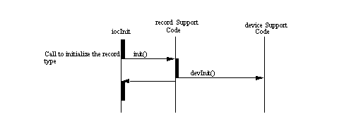
This shows the sequence of events to occur upon initialization of a single instance of the assemblyControl record. This will initialize links and watchdog timer and the device support code. If successful, then the state of the assemblyControl record is IDLE.

In this scenario the DIR directive of MARK is received. This record must be MARKED before further changes in the directive (e.g. to PRESET or START), are acted upon. Any changes in the attributes A-E will also cause the record to be marked.

In this scenario the DIR directive has been changed to PRESET. A check of all input attributes will occur. Possible input attributes are MODE, A-E and the sensors SIJ-SIN. The actual checking of these fields it assembly dependent and could involve translation of the attributes to a named position and velocity. The VAL field will reflect the success or failure of this directive. Upon error, a message will also be supplied.
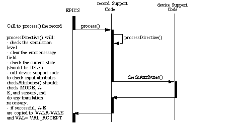
There is an assemblyControl record with 1 to 5 deviceControl records attached. The assemblyControl record receives a directive of START. The individual MODE's will execute different code and are shown in the proceeding sections, just the general receipt of the command is shown here. The directive, mode, position and potentially velocity are passed on to the devices. This assemblyControl record will set its BUSY field to BUSY and not complete until all device records have indicated that they are complete or one of them return an error.
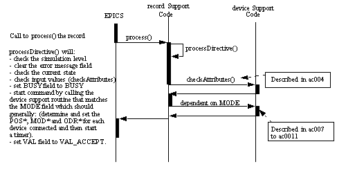
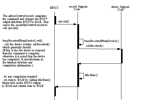
In See ac005 - DIR command of START received with devices attached, a command has been passed on to a deviceControl record(s). This scenario details what happens when one of the attached deviceControl records makes a change in their BUS* field that is attached to this assemblyControl record.
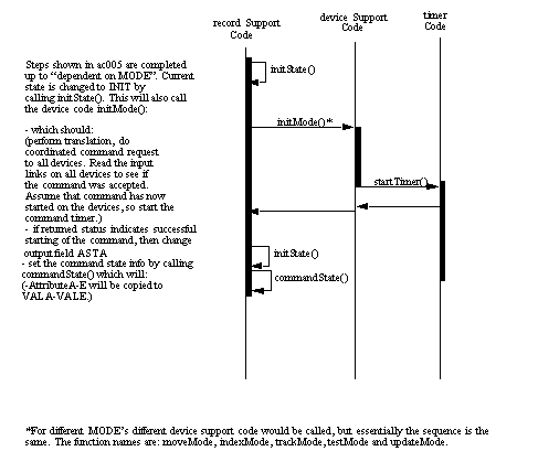
This scenario details the portion of See ac005 - DIR command of START received with devices attached that has the label "dependent on MODE". For this example the assemblyControl record is currently in an IDLE state and an INIT command is received. Input attributes have already been checked and the device support code initMode() is expected to pass the directive, mode, position and potential velocity on to the attached deviceControl record. A timer should be started to indicate when a command has taken too long to complete by the attached deviceControl records. If the timer runs out before all devices have responded to the command, then an associated error should be generated and the BUSY state changed to ERR.
This scenario will not have an event trace as it is identical to "See ac007 - MODE of INIT received", except that the routine "initMode" is replaced by "moveMode".
This scenario will not have an event trace as it is identical to "See ac007 - MODE of INIT received", except that the routine "initMode" is replaced by "indexMode".
This scenario will not have an event trace as it is identical to "See ac007 - MODE of INIT received", except that the routine "initMode" is replaced by "testMode".
This scenario will not have an event trace as it is identical to "See ac007 - MODE of INIT received", except that the routine "initMode" is replaced by "updateMode".
In this scenario the assemblyControl record has started a directive of START and mode of MOVE. The command has not completed, as indicated by the BUSY field indicating BUSY. The directive of PRESET is given with a MODE of TEST. Since the BUSY field does not indicate IDLE or ERR, the VAL field is set to "VAL_REJECT" in response to this request.
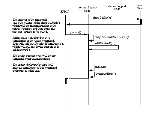
In this scenario the assemblyControl record has previously started a MOVE command, and started a timer. This time is the maximum amount of time allowed for the deviceControl records to complete the command. In this scenario, that time has reached and the record will indicate failure to complete the command.
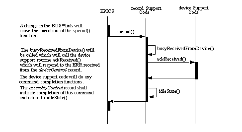
This scenario assumes there are 2 deviceControl records connected to an assemblyControl record. The assemblyControl record has passed on a MOVE command to the 2 device records. If the first device record responds with an ERR then the command is considered to be complete, regardless of the response of the second deviceControl record.

The following sections will define the support routines for both the record and device support modules and then describe the function algorithm. All functions have been listed in See Function List.
The record support routine, as defined by assemblyControlRSET, is the same for every record of this type. The associated functions are:
Only these functions and a few additional ones are described here, as the rest are considered trivial.
This routine is called twice at iocInit. On the first call it returns immediately. On the second call, it does the following:
This routine is called for user specified fields. This routine is called twice, before and after any changes are made for the associated field. On the first call it returns immediately. After the value changes of
A change in device busy fields causes the record to call the record support routine busyReceivedFromDevice(). ( See busyReceivedFromDevice).
The most important record support routine is process. It determines what record processing means. Before calling this routine it is determined if the record is enabled and not currently active, then the following algorithm is processed:
Following are descriptions of routines called from within process:
The following will occur if a fault occurred:
The following will occur if there was a change in BUS1-5:
This function will process directive commands, which include: START, MARK, PRESET, CLEAR and STOP. The START command will have an associated MODE which has possible values of: INIT, MOVE, TRACK, INDEX, TEST, UPDATE, and PARK.
-If currently tracking and are given another tracking command or a move command,
-If currently moving and get another moving command.
-call a device support routine to check input values (See checkAttributes)
-call a device support routine to check input values (See checkAttributes),
-Call device support routine that must act upon the mode set (See The MODE field).
-call a device support routine to stop (See stopDirective). The simulation mode cannot be changed while the BUSY field is not IDLE or ERR.
This routine is called if the field has special processing indicated (SPC_DBADDR) and allows update of the field type, size and data type. This is especially important for the attributes A-E where the datatype is definable.
Returns the engineering units string for display purposes. It returns the value in the EGU field.
This routine gets the precision, i.e. number of decimal places, which should be used to convert the field value to an ASCII string for display purposes. The precision is determined via the Epics routine recGblGetPrec().
This routine fills in the graphics related fields by calling recGglGetGraphicDouble for the related field.
The device support routine, as defined by assemblyControlDSET, is not the same for every record of this type. There will be a standard set of functions that must be available, regardless of their contents. The contents of these functions are configurable. The next section will describe the general functions:
This function is called twice during initialization of the IOC. On the first pass (before records are initialized) it should do any initialization required. The second pass (after records are initialized) should be ignored.
This routine is unique for each assemblyControl record. This function is called once for each assemblyControl record in the system. The general function should be to:
This routine, unique for each assemblyControl record, will check the validity of input attributes and do any translation necessary given the lookup table.
This routine will perform whatever is necessary to stop any action currently being performed.
This routine gets called when one of the deviceControl records connected to the BUS1-BUS5 changes in values. It should:
-If we already received an IDLE from this device then ignore it
-If this is the last device to acknowledge then the command is completed then stop the timer and fill in all appropriate status's to indicate the command is completed
-else this is not the last device to complete the command so just flag that this device is complete and continue on.
All command and status information is passed via the record's device private structure. This communications structure defined in the header file recAssControl.h as follows:
int bus1; /* If set, change in BUS1. */
int bus2; /* If set, change in BUS2. */
int bus3; /* If set, change in BUS3. */
int bus4; /* If set, change in BUS4. */
int bus5; /* If set, change in BUS5. */
int cmdFinished; /* Indiciates cmd is finished. */
SEM_ID cmdLock; /* Timer semaphore. */
int cmdTimedOut; /* Indicates a cmd timedout. */
int debug; /* Current debug mode. */
int fault; /* Indicates a fault occurred. */
int faultCleared; /* Indicates fault not cleared.*/
int lastCommand; /* Last command requested. */
double position; /* Position to move to. */
void *pPrivate; /* Ptr to private dev supp. */
int simulation; /* Current simulation mode. */
long timeout; /* Private timeout flag. */
void *timer; /* Timer callback info. */

The health and simulation of the assemblyControl record is important enough to warrant discussion. Changes in simulation mode are only registered when a command has been initiated and the BUSY field is IDLE. The FULL and FAST simulate modes have been implemented in the deviceControl records and as a result all commands are passed on to the deviceControl records as usual. For VSM simulation mode, commands are not passed on, instead a toggling of the BUSY field is done.
A change in health occurs when an interlock occurs and will not be reset until an INIT command has been issued.
A change in health will occur when an INIT, INDEX or UPDATE command fails.