| UK Astronomy Technology Centre |
Chris Tierney |
| Royal Observatory, Edinburgh |
31st March 2001 |
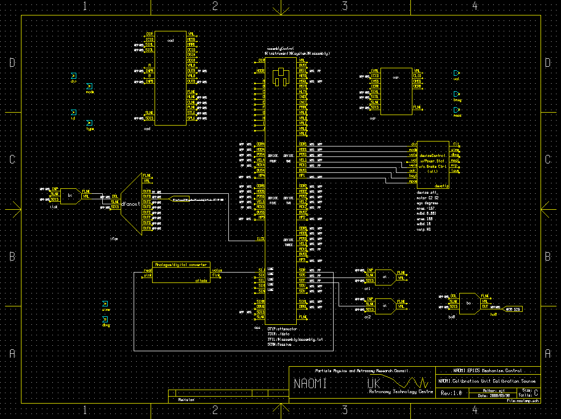
The nculamp.sch schematic

Links from the schematic:
The NCU calibration source consists basically of a lamp (which can be switched on or off) and attenuator mechanism
(a rotating shutter that varies the output intensity of the device). Feedback of the output intensity is given by
a photodiode which is measured, via an anologue-to-digital converter, by the XYCOM-240 card.
Control over the attenautor is acheived using a deviceControl record and OMS card to drive its steppermotor. The
operations of this deviceControl record and of the analogue-to-digital converter (ADC) that reads out the photodiode circuit
are co-ordinated by an assemblyControl record.
The binary output record "bo0" controls the status of the lamp (on or off) via the XYCOM-240 card. It is assumed that,
when indexing or moving the attenuator mechanism via the assemblyControl record (or assemblyControl screen), the lamp
has been switched on already by the user.
The details of the ADC readout software are given in the documentation for the attadc.sch schematic. The assemblyControl
record writes a value on its sensor output field SOR to trigger this software to take a reading, and expects an integer
value to be written to its sensor input field SIJ.
Operation of the assemblyControl record in INDEX mode is as follows:
- As this mechanism has no home or limit switches, the software must derive a suitable place to call the datum position.
It is decided that the attenuator angle that gives the minimum output intensity will be the datum position.
- The assembly begins by setting the deviceControl record into "jog" mode and sending a directive to "go".
- The assembly then periodically triggers a reading of the photodiode output, maintaining a record of both
the maximum and minimum values, and the motor positions at which they were recorded.
- After at least on revolution has been executed, the motor is returned to the position at which the minimum
output intensity was recorded. The maximum and minimum intensities are presented to the user as limits
on the target intensity.
The assembly is operated, after indexing, using the JOG mode of the assemblyControl record. This appears on the DM
screen as a "Hunt" mode button. MOVE mode, for this assembly, simply forwards a position request to the deviceControl
record and reads the current photodiode output.
The behaviour of the assemblyControl record in Hunt (jog) mode is as follows:
- When "hunting" (jog mode), the assembly accepts a demand intensity from the user, and implements a simple search
algorithm to achieve this.
- The demand intensity is read from input field A, and compared with the measured minimum and maximum intensities
(as well as the user imposed upper limit) read from input fields D, E and C respectively.
- If the demand intensity is within limits, the deviceControl record is set into JOG mode (see below for the jog
velocity), and given a directive to start.
- The record periodically triggers a reading from the photodiode software. This is used to periodically update
the jog velocity of the deviceControl record. If the measured intensity is lower than the demand, the required
velocity is positive (otherwise negative). If the measured and demand intensities are close enough in value,
the velocity is lowered. If they are the same, the motor is stopped and the operation is complete.
- Finally, a further reading is taken from the photodiode circuit as a measure of the intensity acheived.

