| UK Astronomy Technology Centre | Chris Tierney |
| Royal Observatory, Edinburgh | 31st March 2001 |

Links from the schematic:
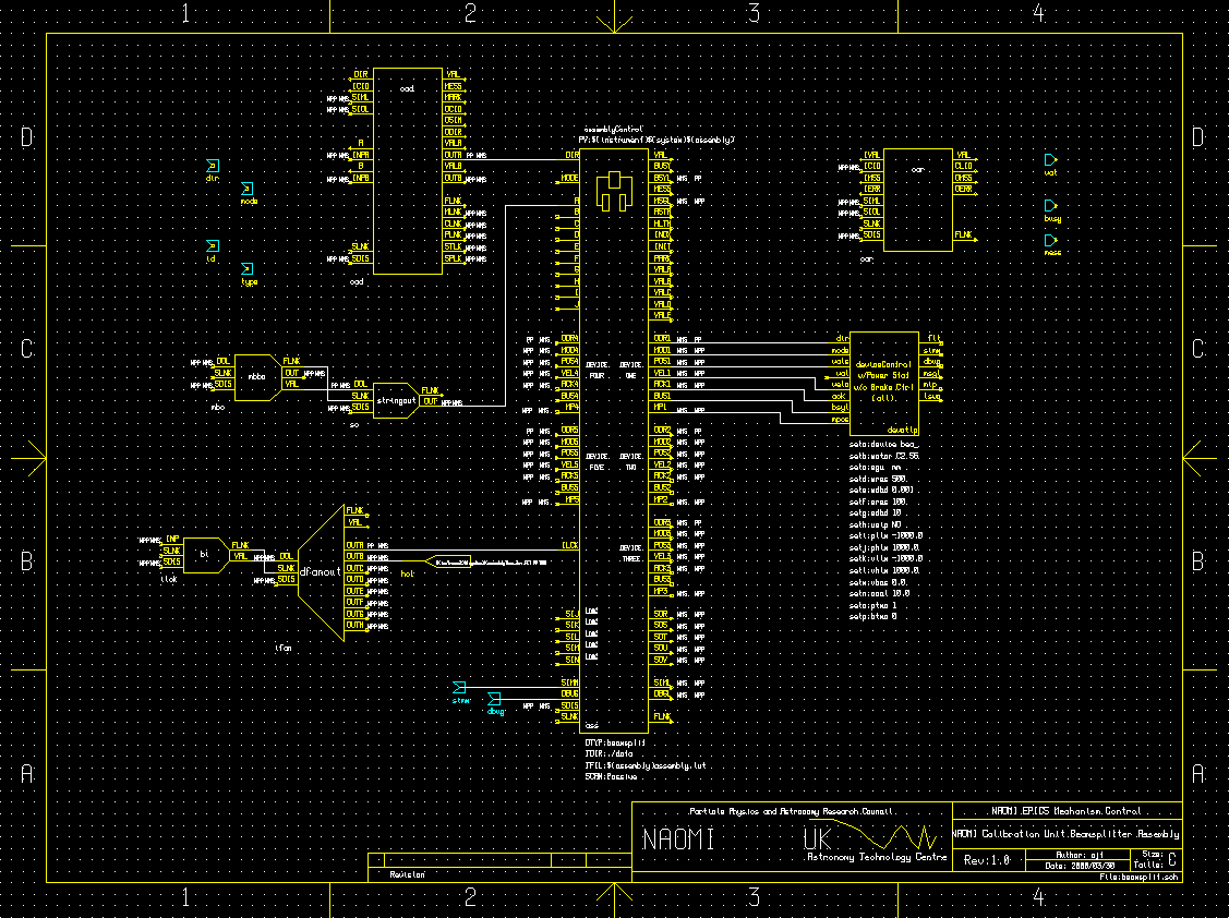
This schematic contains records that control the beamsplitter assembly. The mechanism uses a single steppermotor to drive the beamsplitter optics into, or out-of, the NCU optical path. In normal use, these two positions are acheived by driving the mechanism to its upper or lower limit, respectively.A single deviceControl record provides control over the steppermotor. This, in turn, is controlled by the beamsplitter assemblyControl record. The assemblyControl record, and the sub-schematic containing the deviceControl record, can be seen on the schematic.
When directed to INDEX the mechanism, the assemblyControl record forwards the "ixlow" named position to the beamsplitter device. This causes the mechanism to index to its lower limit switch.
When directed to MOVE the mechanism, the assemblyControl record examines its input field A to determine the demand position. A number found at this string will be interpreted as a target position, in millimeters, relative to the datum/index position. The strings "in" or "IN" are used to signify the in-beam location, and the device will be sent to named position "ixhigh", its upper limit switch. The strings "out" or "OUT" are used to signify the out-of-beam location, and the device will be sent to named position "ixlow", its lower limit switch.
The "mbo" multi-bit binary output record is used, by the beamsplitter assembly DM screen, to provide the strings "in" and "out" to the record.
The "ilck" binary input record collects any interlock signal directed at the assembly. It is passed, via a dfanout record, to both the assemblyControl and deviceControl records. The CAD and CAR records on the schematic are not used. They were included for compatibility with the Gemini standard EPICS interface that was not required.