


Ultimately, the information contained in an optical image can be expressed as the spatial and temporal variation in the number of photons. The problem of detecting and recording such an image is then essentially one of counting the number of photons in each image element.
The way in which the IPCS does this is shown schematically
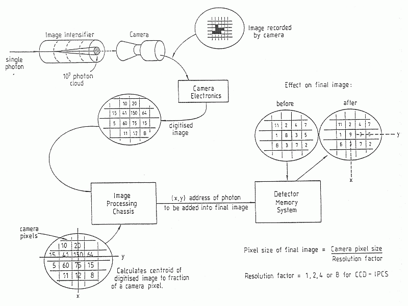
in Figure  , and can be described in very general terms as
follows: individual photon events are detected by
means of an image intensifier, on the front of which is mounted a
photocathode. Photons incident on the photocathode result in
the emission of an electron. Each of these
electrons triggers a cascade of electrons through
the image intensifier, producing a signal of order 10
, and can be described in very general terms as
follows: individual photon events are detected by
means of an image intensifier, on the front of which is mounted a
photocathode. Photons incident on the photocathode result in
the emission of an electron. Each of these
electrons triggers a cascade of electrons through
the image intensifier, producing a signal of order 10 electrons at the output. This splash of electrons
is detected by a TV camera, and passed to a hardwired
image processing unit which calculates the centroid
of each splash, and hence the position on the photocathode
of each photon event. The (x,y) coordinates of each photon event
are then passed to the Detector Memory System (also known as the
External Memory), which counts the number of photons detected
in each pixel by incrementing an appropriate memory location.
During the course of an integration, a 2-dimensional image
or spectrum is built up in the Detector Memory System.
In fact, the image can have more than two dimensions, since
in addition to assigning each photon event an (x,y) coordinate,
the events can be ``tagged'' with a third number (e.g. etalon gap
for observations with TAURUS, UT for observations with high time
resolution, Stokes parameter for polarimetric observations).
electrons at the output. This splash of electrons
is detected by a TV camera, and passed to a hardwired
image processing unit which calculates the centroid
of each splash, and hence the position on the photocathode
of each photon event. The (x,y) coordinates of each photon event
are then passed to the Detector Memory System (also known as the
External Memory), which counts the number of photons detected
in each pixel by incrementing an appropriate memory location.
During the course of an integration, a 2-dimensional image
or spectrum is built up in the Detector Memory System.
In fact, the image can have more than two dimensions, since
in addition to assigning each photon event an (x,y) coordinate,
the events can be ``tagged'' with a third number (e.g. etalon gap
for observations with TAURUS, UT for observations with high time
resolution, Stokes parameter for polarimetric observations).
[ TIFF ]
Figure: A schematic representation of how photons are counted
by the IPCS
The IPCS can be broken down into the following components:
.
It can be seen
that the peak efficiency is about 20 per cent at a wavelength of
4000 Å. The efficency is poorer in the red, falling to about
5 per cent at 6500 Å and less than 1 per cent beyond 8000 Å.
 . The intensifier
is manufactured by EMI, and is frequently referred to as the
``EMI-tube''. The usable area is about 40 mm in diameter, although
the unvignetted area passed by the UES camera is 38.5
. The intensifier
is manufactured by EMI, and is frequently referred to as the
``EMI-tube''. The usable area is about 40 mm in diameter, although
the unvignetted area passed by the UES camera is 38.5  18.8 mm.
Granularity of the available tubes has been measured
at RGO to be 3 per cent rms; granularity due to intermediate
photocathodes is diminished to around 1.5 percent rms by magnetically
scanning the image inside the EMI-tube to reduce the effects of
variations of these photocathodes. The scanning system used is
described by Jorden, A.R. & Fordham, J.L.A. (QJRAS, vol 27, p166,
1986)
The intensifier is protected from variations in the local magnetic
field by a mu-metal shield.
18.8 mm.
Granularity of the available tubes has been measured
at RGO to be 3 per cent rms; granularity due to intermediate
photocathodes is diminished to around 1.5 percent rms by magnetically
scanning the image inside the EMI-tube to reduce the effects of
variations of these photocathodes. The scanning system used is
described by Jorden, A.R. & Fordham, J.L.A. (QJRAS, vol 27, p166,
1986)
The intensifier is protected from variations in the local magnetic
field by a mu-metal shield.