

Next: Performance
Up: Utrecht Echelle Spectrograph
Previous: Overview
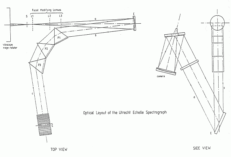
The layout of the spectrograph is shown schematically in Figure  . The slit
S is at the focal plane of the telescope. The light from the slit image (beam
a) is collimated (beam b) by an off-axis parabolic mirror C, and traverses the
three cross-dispersing quartz prisms P1, P2 and P3 before beam c is incident on
the echelle grating E. The axes of
beams a, b and c are horizontal. The light is dispersed in the vertical plane
(beam d) by the echelle grating (beam d) and is finally re-imaged by the
camera.

[ TIFF ]
Figure: Schematic
of the Utrecht Echelle Spectrograph (UES).
The main components are as follows:
- Slit unit. The scale at the slit is 4.44 arcsec mm
 (1
arcsec = 225
  m)
m) . The slit has a maximum length of
5 arcmin; a dekker of continuously variable width is used to define the slit
length. The slit width can be set to between 0.09 and 90 arcsec. The entire slit
assembly can be rotated from -12 to +11 degrees relative to the nominal
position; this is required to ensure that the slit image is perpendicular to the
direction of dispersion (along the spectral orders). A shutter is mounted at the
rear of the slit. The slit jaws are polished so that they can be viewed with the
acquisition TV or by the autoguider.
- Collimator. There is a choice of two collimators which can be
selected remotely. One collimator has been coated for best performance at
wavelengths below 4000 Å, while the other is silver coated for high
reflectivity longwards of 4000 Å. The collimators are off-axis paraboloids
with focal length of 2359 mm; the diameter of the collimated beam is 215 mm. A
Hartmann unit is available in front of the collimator assembly for focusing the
spectrograph.
- Cross-dispersing prisms. Unlike most other echelle spectrographs
in use on 4-m class telescopes, UES uses prismatic cross-dispersion to separate
the echelle orders. The reasons which led to this choice are discussed in the
article by Walker & Diego referenced above. Compared with grating
cross-dispersers, prisms offer the advantages of higher efficiency and more
uniform inter-order spacing. In order to maintain high efficiency down to
3000 Å, the UES prisms are made of extremely homogeneous fused silica.
However, the prism size demanded by the optical design is beyond the limits of
current manufacturing technology. In order to provide sufficient
cross-dispersion, three smaller prisms are used in series; each prism is in
turn composed of three smaller units optically contacted together by means of a
UV transmitting fluid.
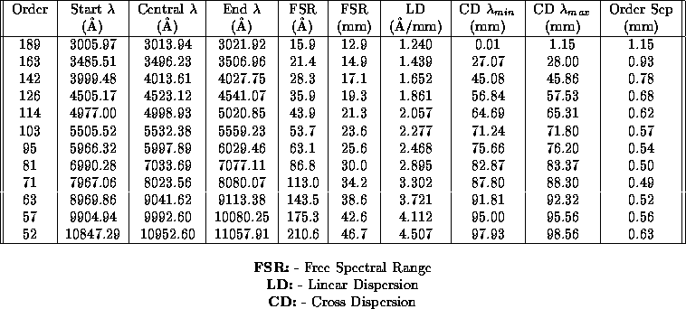
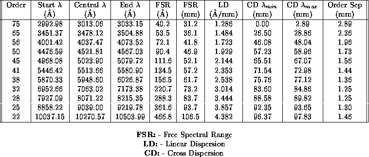
- Echelle grating. Two are available (and remotely selectable). Both
were manufactured by Milton Roy, have ruled area of 204
 408 mm and
nominal blaze angle of 63.4 degrees. One echelle grating has a ruling of 31.6
grooves/mm, while the other has 79 grooves/mm. The spectral
formats produced by the two echelle gratings are detailed
in Tables
  and
and  .
.
Both echelles provide the same linear dispersion at the detector, and
therefore the same resolving power for a given slit width. However, the free
spectral range of the former is 2.5 times shorter than that of the latter;
consequently, the spectral orders are 2.5 times closer together with 31.6 than
with the 79 grooves/mm echelle grating. Thus, the 31.6 ruling is the
preferred choice when continuous wavelength coverage of the echelle orders is
the overriding consideration, while the 79 is the grating most often used for
observations requiring accurate registration and subtraction of the sky signal
along the slit (the maximum slit length which can be accommodated with the 79
grooves/mm echelle is 2.5 times greater than with the 31.6).
- Camera. This is of folded Schmidt design with a field flattener
lens, and is described by Wynne 1977 (MNRAS, 180, 485).
The focal length is 700 mm. The nominal, unvignetted field of view is
 mm, the longer dimension being along the echelle orders.
- Detectors. Any of the detectors available on the WHT (see Chapter
 ) can be mounted on UES. The most commonly used detector is one of the thinned
Tektronix chips, which has a high
efficiency over a broad range of wavelengths. For observations of faint objects
the IPCS is the detector of choice, because of its extremely low dark count and
lack of read-out noise. Note that of the detectors currently available, only the
IPCS, with its 10 micron pixels, can sample the full resolving power of UES.

Table: Spectral Format of the 31.6 grooves/mm Echelle Grating
--- Sample Orders

Table: Spectral Format of the 79 grooves/mm Echelle Grating ---
Sample Orders


Next: Performance
Up: Utrecht Echelle Spectrograph
Previous: Overview
Tue Aug 15 16:42:46 BST 1995
 . The slit
S is at the focal plane of the telescope. The light from the slit image (beam
a) is collimated (beam b) by an off-axis parabolic mirror C, and traverses the
three cross-dispersing quartz prisms P1, P2 and P3 before beam c is incident on
the echelle grating E. The axes of
beams a, b and c are horizontal. The light is dispersed in the vertical plane
(beam d) by the echelle grating (beam d) and is finally re-imaged by the
camera.


 (1
arcsec = 225
  m)
m)
 408 mm and
nominal blaze angle of 63.4 degrees. One echelle grating has a ruling of 31.6
grooves/mm, while the other has 79 grooves/mm. The spectral
formats produced by the two echelle gratings are detailed
in Tables
  mm, the longer dimension being along the echelle orders.

