| THE ING NEWSLETTER | No. 5, October 2001 |
|
|
SCIENCE |
|
|
|
| Previous: | First Light on the New Small Fibre Module of Autofib2/WYFFOS | Up: | Table of Contents | Next: | First Results from the Rayleigh Laser Guide Star Project |
Other available formats: PDF
The ING Red Sensitive CCD Project
Simon Tulloch (ING)
This project aims to improve the red sensitivity of our instruments through the use of low-fringing high-Quantum Efficiency (QE) CCDs. These are being produced by MIT Lincoln Labs for a consortium of observatories. Gerry Luppino manages the consortium at the University of Hawaii. His Company, GL Scientific, is providing CCD packages and cables. The ING commitment to the consortium is $141,000. This will give us at least three science grade devices.
The wafers will be divided
and put through two different processes. The first process, called BIV,
will give excellent red response but very poor blue performance. The second
process, called UV or MBE, will improve the blue response whilst leaving
the red response intact. The MBE process is still being developed (as of
spring 2001). We have requested that our first chip be from the BIV process.
This chip will be used at ISIS RED as its blue response is not important.
Our subsequent chips will hopefully come from the MBE process, depending
on its success. Two of these devices will be incorporated into a mosaic
camera for use with WYFFOS long, UES and possibly for prime focus imaging
on the WHT. If the wafer run has good yields we can expect a fourth device
for use with OASIS. Additional sources are being investigated for a fourth
chip should the yields from this contract be lower than expected.
| CCD Characteristics
Size: 2048 × 4096 pixels
Two outputs with a high sensitivity of 15µV/e Fringing at 1000nm £ 10% Manufactured from 40-micron thick high-resistivity silicon |
The Physics of Deep Depletion CCDs
Standard thinned CCDs are
typically 15 microns thick. As the wavelength approaches 1 micron, the
absorption depth of silicon increases rapidly and the CCD becomes transparent.
The red sensitivity suffers accordingly. There is an additional problem,
called 'fringing' which in some applications is an even more serious drawback
than poor QE. As the transparency of the chip increases at longer
wavelengths the CCD acts as a Fabry-Perot cavity with light reflecting
back and forward between the front and rear surfaces. Interference is produced
that heavily modulates the spatial uniformity and reduces the SNR of the
observations. The solution is to make the CCDs thicker than the absorption
depth of the silicon, incident photons will then be absorbed on their first
pass and reflection from the rear surface will be greatly reduced. Our
CCDs will be 40 microns thick. Standard silicon cannot be used for this
process since it cannot sustain the high electric field throughout the
full depth of the device that is so important for good QE. Instead a special
grade of high-purity high-resistivity silicon must be used.
 |
Figure 1. Image showing the effects of fringing in a thinned astronomical CCD. [ GIF | TIFF ] |
Latest Quantum Efficiency Data
QE data is available for
the BIV CCD with a broad band coating. The red response is impressive;
up to three times better than a thinned EEV. QE data on the MBE (blue boosted)
CCD is only available for a device with an anti-reflection coating optimised
for the blue. The red response of this device is not fantastic but should
approach that of the BIV, once a broad band coating is applied. Marconi
have also started to produce deep depletion CCDs, and the QE of their device
is shown in Figure 2.
 |
| Figure 2. Quantum Efficiency comparison between current and new red CCDs. [ GIF | TIFF ] |
The first of the ING cameras
is complete and awaiting the delivery of the first CCD. For additional
information, please see the project web site : http://www.ing.iac.es/~smt
/redsense/redsense.htm.
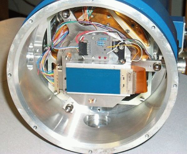 |
Figure 2. A photo of one of the ING cameras (with a test chip mounted) complete and awaiting the delivery of the first red CCD. [ JPEG | TIFF ] |
Email contact: Simon Tulloch (smt@ing.iac.es)
| Previous: | First Light on the New Small Fibre Module of Autofib2/WYFFOS | Up: | Table of Contents | Next: | First Results from the Rayleigh Laser Guide Star Project |
| GENERAL | SCIENCE | TELESCOPES AND INSTRUMENTATION | OTHER NEWS FROM ING | TELESCOPE TIME |