- Greimel, R., Lewis, J. R., Walton, N. A., 2001, ING Newsl, 4 (this issue). Citation in text
- Ives, D. J., Tulloch, S. M., Churchill, J., 1996, Proc SPIE, 2654, 266. Citation in text | ADS
- Leach, R. W., Beale, F. L., Eriksen, J. E., 1998, Proc SPIE, 3355, 512. Citation in text | ADS
- Lewis, J. R., Walton, N. A., 1998, Proc SPIE, 3349, 263. Citation in text | ADS
- Rixon, G. T., Walton, N. A., Armstrong, D. B., Woodhouse, G., Tulloch, S. M., 2000, Proc SPIE, 4009, 132. Citation in text | ADS
- Walton, N. A., Bunclark, P. S., Fisher, M. P., Gribbin, F. J., Jones, E. L., Rees, P. C. T., Rixon, G. T., 1998, Proc SPIE, 3351, 197. Citation in text | ADS
- Walton, N. A., Rixon, G. T., 2000, ING Newsl, 3, 31. Citation in text
| THE ING NEWSLETTER | No. 4, March 2001 |
|
|
THE ING WIDE FIELD IMAGING SURVEY | SCIENCE |
|
|
|
| Previous: | Science Highlights from the ING Wide Field Survey | Up: | Table of Contents | Next: | Pipeline Data Processing |
Other available formats: PDF | gzipped Postscript
|
The
Wide Field Camera and Infrastructure
Nicholas A. Walton, Daniel J. Lennon, Robert Greimel (ING) and Mike J. Irwin, James R. Lewis, Guy T. Rixon (IoA) |
THE ING WIDE FIELD IMAGING SURVEY |
1 The Wide Field Survey Infrastructure
1.1 The Wide Field Camera
The Wide Field Camera
(WFC) was originally envisaged as a system containing four 2k×2k
Loral devices (Ives
et al., 1996) and was commissioned in this format during May 1997.
Unfortunately the Loral devices never functioned to specification, thus
in 1997, it was decided to retrofit the camera with 4k×2k EEV42 devices.
The large format of these involved a redesign of the mounting system within
the WFC, and enabled effectively the entire field of view provided at the
prime focus of the INT to be imaged. The 'new' WFC was commissioned at
the INT in April 1998. Figure 1 shows the WFC.
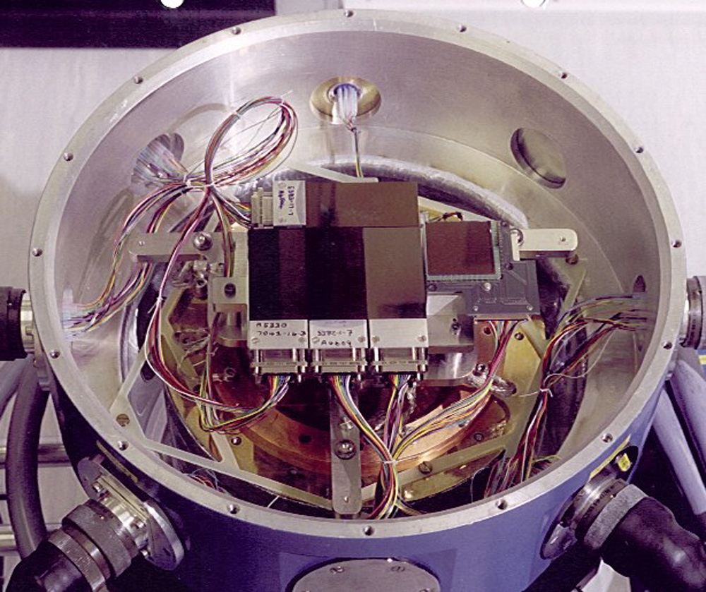 |
| Figure 1. This image shows the four EEV science CCDs in the open dewar. The square CCD to the right is the Loral CCD used for auto-guiding. Each EEV is approximately 28mm×56mm in size. [ JPEG | TIFF ] |
The WFC's auto-guider system, employing a Loral 2k×2k CCD operating in frame transfer mode, is mounted on the same baseplate as the science CCDs. It views the edge of the WFC field through the same filter as being employed for the observations. This has the disadvantage that guide stars may sometimes not be available in the U band. However, it does mean that the geometry of the guider with respect to the science CCDs is extremely stable, thus aiding (re)acquisition and guiding.
2 The UltraDAS
The advent of large detector arrays was a main driver towards the implementation of a more sophisticated data acquisition system (UltraDAS) to replace the legacy DAS system. This included the introduction of an interim data acquisition system that was a pre-cursor to UltraDAS (Walton et al., 1998). The UltraDAS was designed with the intention to support all ING optical and infra-red detectors, and to enable specialist modes such as high-speed photometry (Rixon et al., 2000) and was implemented at the WFC in September 1999. The UltraDAS produces FITS format files using the Multi-Extension FITS (MEF) format. This is further discussed by Walton and Rixon (2000).
2.1 UltraDAS Design
The primary concern with UltraDAS was that it enables silicon limited readout speeds. The 4×2k detectors in use at the ING are designed with maximum readout speeds of a few microsecs/pix, implying a readout time of some 30sec for the full CCD. The HgCdTe array employed in INGRID can have frame rates of a Hz. UltraDAS delivers these readout speeds.
The UltraDAS client-server
architecture (see Figure 2) was designed such as
to be common for all ING detectors. However, the system is structured so
as to be adaptable to meet current and possible future detector requirements.
The UltraDAS commands can be called from shell scripts, as can the telescope,
auto-guider and instrument commands. This facilitates semi-automated observing.
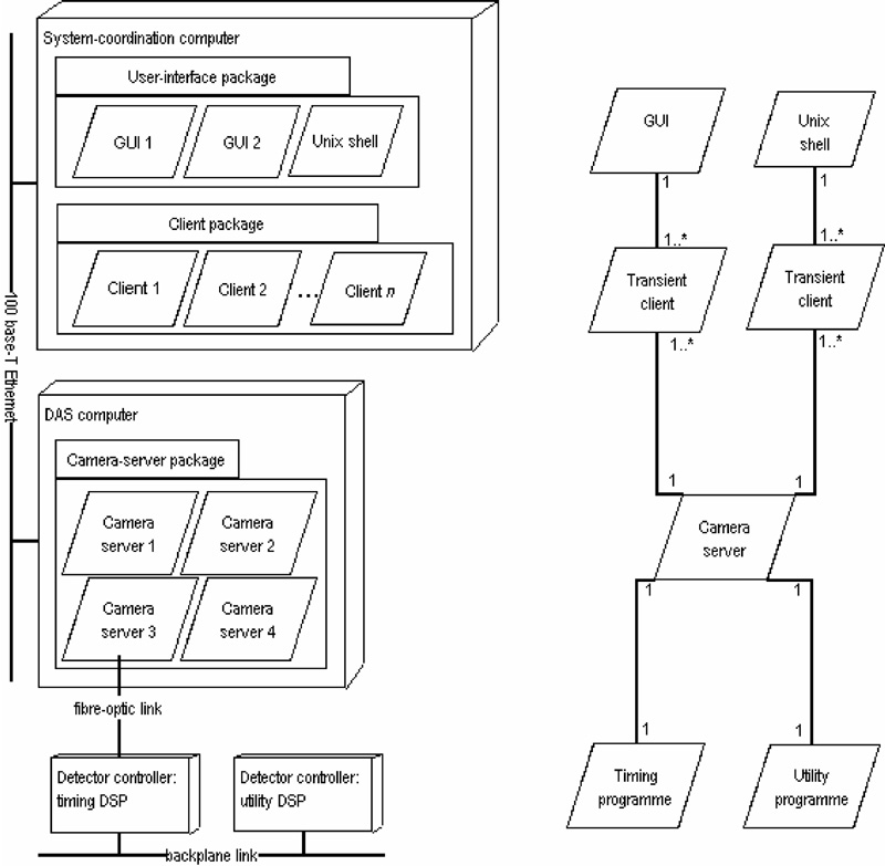 |
| Figure 2. The left hand chart shows the WFC hardware network, whilst the right hand chart represents the UltraDAS client layering. [ JPEG | TIFF ] |
2.2 The SDSU Controllers
The detector control electronics forms the heart of the DAS. UltraDAS employs the Generation-2 detector controller from the CCD laboratory at San Diego State University (SDSU-2 controllers) (Leach et al., 1998). The SDSU-2 controller is a highly-programmable device enabling the hardware to be standard and interchangeable. A few boards in the SDSU-2 controllers are different for IR and optical applications. All the specialisation and tuning for a particular detector is in code that is held on the unix computer-network and downloaded at each reset of the controller.
The SDSU-2 controllers communicate over fibre-optic pairs to a PCI based interface board in a SUN SPARCstationTM. The board provides a >16 Mpixel buffer and this reduces the real-time IO requirements when processing the data flow. As of February 2001, the PCI interface drivers have not been brought into operation, thus the system currently runs via a SBUS interface card with somewhat increased readout processing overheads resulting.
The SDSU-2 controllers coupled with UltraDAS ensure that the ING detectors are silicon limited on readout, with no extra overheads being added due to the processing data acquisition software.
3 The Observing Control System
To support the implementation of the new UltraDAS and the WFC, the observing control system was updated (Walton et al., 1998). This involved modernisation of the Telescope Control System (TCS). The Instrument Control System (ICS) for the WFC includes integrated ICS and DAS functionality. All control sub-systems (e.g. the DAS, TCS, ICS for the WFC, auto-guider control, etc.) have been integrated into a unified system. The implementation allows for automated control of the WFC with the INT.
The WFC was the first instrument at the ING where the servers controlling the telescope, auto-guider, instrument and detectors all have common interfaces and can be controlled in parallel from one client-programme. This has enabled a number of observing tools to be implemented. The SMARTFLAT utility uses the INT's prime-focus auto-guider as an exposure meter for taking flat-field observations in twilight, whilst the FOCUSRUN utility is employed to determine the best telescope-focus.
4 Integration with the ING Data Management System
A key design consideration in the design of the UltraDAS was that it should be compatible with the ING's Data Management System (DMS) (Lewis & Walton, 1998). The UltraDAS is thus architecturally integrated with the DMS, ensuring that the WFC data generated is available to be pipeline processed and archived in both the ING's science (http://archive.ast.cam.ac.uk/ingarch) and engineering archive systems (http://orion.roque.ing.iac.es/ing_eng).
The processing flow of WFC data is described more fully by Greimel et al. (this issue). Their article covers the pipeline processing system developed for WFC imaging data, the 'Gigawulf' processing unit implemented to power the pipeline and the data's integration into the archiving system.
4.1 Quality Control
The reduced data products from the WFC have an operational benefit in addition to their scientific worth. A number of key quality control performance measures are extracted on a nightly basis from the generated object catalogues. These indicators include instrumental information such as sky brightness levels, image quality (ellipticity, FWHM of images), and throughputs from extraction of standard star fluxes and comparisons with known zero point data. An example of can be seen Wide Field Survey Release 0.1 at http://www.ast.cam.ac.uk/~wfcsur/release.summary. The quality indicators enable early feedback as the functional performance of the WFC.
5 Closing Remarks
The WFC is now fully operational in a stable state at the INT. Later in 2001 UltraDAS will be upgraded to run with the PCI interface cards (as opposed to the SBUS cards currently used), resulting in somewhat reduced readout overheads (the readout time will remain as now, but associated readout processing overheads will fall dramatically).
For the future, the observing scripts will be standardised, with calibration scripts, for example, offered to observers. With the move to more survey style observing, it is envisaged that routine calibration sequences will be carried out via these scripts.
Acknowledgements
The authors would
like to thank the many people who have worked to make the Wide Field Camera
and the associated control data systems the success that they have proven
to be.
References:
Email contact: Nic Walton (naw@ing.iac.es)
| Previous: | Science Highlights from the ING Wide Field Survey | Up: | Table of Contents | Next: | Pipeline Data Processing |
| GENERAL | THE ING WIDE FIELD IMAGING SURVEY | SCIENCE | TELESCOPES AND INSTRUMENTATION | OTHER NEWS FROM ING | TELESCOPE TIME |