

Next: Telescope control
Up: The 1.0-m Jacobus
Previous: Summary of mechanical
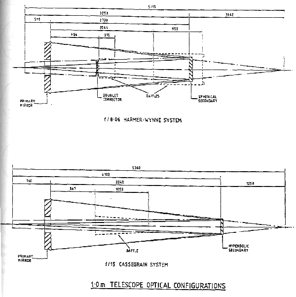
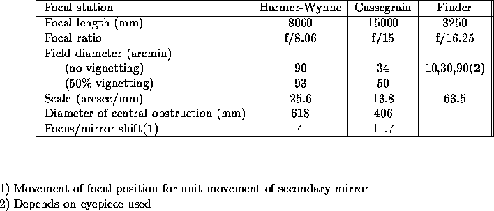
Details of the individual optical elements are collected in Table
 . Table
 gives the most important parameters of the two optical configurations
available, illustrated in Figure
  .
The two optical systems share the same
parabolic primary, with a clear diameter of 1.000 m and a focal length of
4.596 m. Two secondary mirrors are available on interchangeable top ends, as
follows:
(a) a spherical secondary which, together with the primary mirror and an
afocal doublet, constitutes the f/8.06 Harmer-Wynne system described in
Monthly Notices of the Royal Astronomical Society, vol 177, p25p
1977. This configuration gives
a highly corrected flat
focal plane, 90 arcmin in diameter, located 515mm behind the primary mirror.
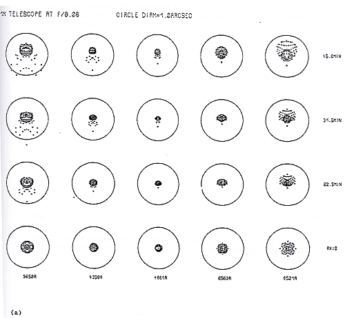
The angular scale is 25.6 arcsec/mm. As can be seen from the spot diagrams
reproduced in Figure
 , this system gives images smaller than 0.5 arcsec in
diameter over the unvignetted field for incident light wavelengths in the
range 3650 Å to 8521 Å. It is not envisaged that the f/8.06 focus would
normally be used without the corrector; astronomers interested in using this
system for non-standard applications (as for example with their own
instruments) should discuss their requirements with RGO staff.
(b) a hyperbolic secondary constituting, with the primary, a conventional
f/15 Cassegrain system. The curved focal surface is located 760 mm behind the
pole of the primary mirror, giving a 34.4 arcmin diameter field with a scale
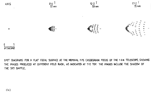
of 13.8 arcsec/mm. As shown in Figure
 , the total aberrations on a flat
focal surface passing through the nominal focal position on axis are
calculated to be up to about 2 arcsec in diameter over the unvignetted field.
Clearly, the off-axis images can be slightly improved by focussing the
telescope at a compromise position for the field of view of interest.
The maximum movement of the secondary mirrors is  20 mm
about the nominal focus position. For the f/15 system
this produces a shift of 241 mm about the optimum focal position; the on-axis
image size is calculated to grow approximately linearly with focus shift up to
a maximum diameter of 0.3 arcsec. Use of the Harmer-Wynne f/8.06 system at
other than the nominal focal position is not recommended without prior
ray-tracing.

Figure 2.21: Optical
layout of the JKT, showing the f/8.06 Harmer-Wynne and
f/15 Cassegrain configurations [ TIFF ].

Table: Summary of mirror characteristics for the JKT

Table: Optical characteristics of JKT foci


Figure 2.22: (a)
Spot diagrams for images at the f/8.06 focus of the JKT for
various wavelengths and field radii. The diameter of the
circle is 1.0 arcsec. [ TIFF ]. (b) Spot diagrams for a flat surface at the f/15 Cassegrain
focus of the JKT [ TIFF ].


Next: Telescope control
Up: The 1.0-m Jacobus
Previous: Summary of mechanical
Tue Aug 15 16:42:46 BST 1995
 . Table
 gives the most important parameters of the two optical configurations
available, illustrated in Figure
  .
The two optical systems share the same
parabolic primary, with a clear diameter of 1.000 m and a focal length of
4.596 m. Two secondary mirrors are available on interchangeable top ends, as
follows:


 20 mm
about the nominal focus position. For the f/15 system
this produces a shift of 241 mm about the optimum focal position; the on-axis
image size is calculated to grow approximately linearly with focus shift up to
a maximum diameter of 0.3 arcsec. Use of the Harmer-Wynne f/8.06 system at
other than the nominal focal position is not recommended without prior
ray-tracing.


