The slit jaws are polished so that reflected light can be passed back up to the TV camera in the A&G box for SLIT VIEWING. See A&G box.
The SLIT SHUTTER is driven from a solenoid valve operating a pneumatic piston. This is the main shutter for the IDS and NOT the camera shutters which serve only as dark slides. Originally, the slit shutter was driven from the IDS MMS controller. This is no longer the case. A connection is now made to the MMS controller from the SDSU shutter control module. The slit shutter board in the controller has been modified and now only acts as a buffer for shutter control. Hettich switches provide the OPEN and CLOSE status signals.
The DEKKER unit (named after an American astronomer who first came up with the idea) consists of a slide fitted with a Dekker mask above the slit jaws. The Dekker mask consists of a series of polished plates with accurately machined slots designed to produce an aperture across the slit of a known value in arcseconds. Several Dekker masks are available for the IDS (some with different sized slots and others with combs) that can be interchanged through the Observers Port (SLIT) door.
The Dekker slide is moved by a stepper motor and has upper and lower limit (Hettich) switches fitted. The position is encoded using a Penny Giles pot; the output going to a signal conditioning card in the MMS controller. A friction pad driven by a pneumatic valve acts as a clamp.
It should be noted that the ICS software has ability to change the value that determines the definitive Dekker positions, 1, 2, 3 etc. thus small corrections can be made to where the mask will position itself over the slit.
The Slit and Dekker assembly can be removed and replaced with a Multi-slit
assembly consisting of ten parallel slit-lets each 16 arcsec long with
a 7 arcsec seperation. This was mainly used with the FOS.
The slides are moved using pneumatic pistons controlled by solenoid
valves. Hettich inductive slotted switches operated by a flag on the slide
determine the filter position. Another Hettich sensor serves as a detent
switch and operates when a filter is in a valid position.
The collimator is mounted on a high resolution linear drive and driven by a stepper motor. A high accuracy A.S.L. linear transducer measures the position. The output also going to the signal conditioning board in the MMS controller. When movement has stopped, solenoid valves operating pneumatic clamps lock the collimator drive to prevent any flexure.
IMPORTANT: It should be noted that the actual movement
of the collimator +/- (where the beam is still parallel) is small,
thus the CCD cryostat needs to be mounted as such that the IDS focus falls
approximately mid way within the collimator range of movement.
The grating consists of a optically flat plate with rulings; the spacing depending on the dispertion required. Some gratings can have as much as 600 lines per millimetre or more. Several gratings are available of both low and high dispertions for the IDS. The spectrograph is 'tuned' to the required wavelength by changing the angle of the grating with respect to the collimated beam.
The grating is mounted into a kinematic seat to ensure optical alignment and clamped to prevent movement. n.b. It should be noted that the grating can be inserted in TWO ways. This enables the BLAZE angle created by the rulings to point to the camera in use (235 or 500). An arrow on the grating should point either to the left (500) or right (235) depending on what camera is is use.
The grating angle to wavelength relationship is critical thus the position angle must be known to a high precision. This is achieved used an Ferranti 20 bit absolute intelligent encoder with a resolution of 0.001o complete with error checking built into the serial data string. This is decoded by the IDS controller and used in the final positioning of the grating. However, if the error checking bits are set then the resolution decreases by a factor of 1000 i.e. to only 1o resolution.
Due to failure of the Ferranti encoder and not having a reliable spare one, it was decided to replace this device with with and INDUCODER 16 - bit absolute encoder with SSI output. The description of this project can be found here. The new encoder emulates the old Ferranti encoder and has some additional features included.
When changing the grating, the grating shutter moves across the
beam and the grating carrier moves parallel to the door of the Grating
Port to allow access. As with the slit and collimator observer access
ports, the grating port door is interlocked (solenoid clamped) to prevent
light leaks. An ids_change command must be issued to unlock
any doors on the IDS.
Solenoid operated pneumatic valves and pistons operate the camera shutters
(dark slides) and were designed in such a way to automatically close on
the press of a panic button in cases such as high illumination on the detectors.
Again, a throw-back from the IPCS era. However, it is important that the
IDS camera port NOT in use has its shutter closed. If a cryostat is NOT
fitted to an used port, light could enter and ruin the observations.
All mechanisms that use stepper motors are controlled by double
height
eurocard boards (one for each motor) which contains the motor coil
phase
switching and power (4 transistors) circuits. A 6821 PIA chip
handles
the input signals from the IDS mechanism's associated position sensors
and limit switches (Hettich slotted inductive switches) and also
provides
the direction and speed TTL toggles to drive the motor circuits. The
velocity
ramp up/down of the stepper motors is done using hardware. More
information on these Stepper Motor Drive boards and the differences
between them can be found here. There are also preliminary investigations and conclusions done by John Mills, his report is here.
As this instrument uses pneumatic values to control some mechansims, special PIA cards with interface circuitry are installed in the crate. A Signal Conditioning board is also present which handles the data from the SLVC transducers.
Serial communications to the 6850 ACIA board in the MMS is via an RS232
link (9600 7E1). There are two ports, one for engineering the other
for computer
control. Generally only the computer port is
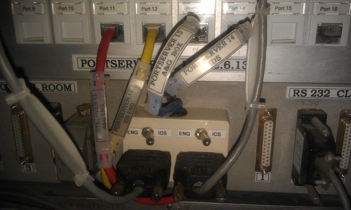
used. The RS232 connection runs to a panel mounted on the CASS
electronics
rack where control can be switched between two ports on a PORTSERVER,
port 14
which is the ICS computer accesses over the network, or port 12 which is a
Virtual PC accesses over the network for engineering use. This Virtual
PC is a Linux machine running on taurus with a dosbox
running the CDSAI Engineering software. The Virtual PC can be
accesed by starting a VNC-Viewer session on your computer, then connect
to: idsconsole:1 with the password: ******** A small box mounted on the panel fitted with
a switches selects to where the comms line is routed. See the picture below or Cassegrain
Interconnections drawing for more details.
n.b. Although only full I/O control with the PC is enabled with the switch in the PC position. When control is via the Portserver, the PC can still read incoming data and will show if a mechanism has moved. A useful diagnostic.
Here is an image of the Engineering software user interface:
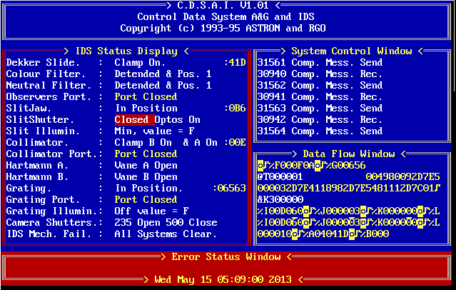
In case you see the DOS C: prompt instead of the above screen, you
can start the program by typing: cdsai <return>. If the screen is
present but not updating and no data scrolling then call someone from
the CFG group to restart the virtual machine idsconsole:1
(161.72.36.158). If the screen is present but the Error Status Window
says that there is no respons and there is no data scrolling in
the Data Flow Window, the instrument is switched off. This can be
switched on remotely by entering the INT Cass APC webserver.
References: