Acquisition and Guider (A&G) Box
The Acquisition and Guider box has been designed primarily for use with
the Intermediate Dispersion Spectrograph (IDS) and the Faint Object Spectrograph
(FOS). Nevertheless, the overall philosophy of the design has been to incorporate
a range of facilities which can be used by almost any instrument operating
at the Cassegrain focus.
Acquisition
A Westinghouse extended S20 cathode high gain TV camera views a 1.8 * 1.8
arcmin segment of the 20 arcmin diameter Cassegrain field in the ON-AXIS
(field viewing) or OFF-AXIS (slit viewing) positions.
The TV is mounted on an linear worm drive X-Y carriage driven by stepper
motors and can gain access to any part of the Cassegrain field. For slit
viewing, the TV is left in its centred position.
The TV is fixed to an adjustable focus plate on the carriage which allows
for re-focusing if the TV is changed or another instument is mounted at
CASS which requires a different focus. The TV is nominally focused on the
slit
jaws of the IDS. A filter wheel is available for the TV camera allowing
up to four choices of filters.
To acquire an object, the TV acquistion probe; which is fitted with
a FLIP MIRROR, can be in one of two positions:
-
FIELD viewing
The FLIP MIRROR moves into the beam at 45o thus allowing
the TV to view the field directly from the secondary mirror.
-
SLIT viewing.
The FLIP MIRROR is left out of the beam and transfer optics in the
TV probe feed light to the TV camara that is reflected from the
polished angled slit jaws of the IDS. This enables science observations
to be carried out whilst giving confidence that the object is centred on
the slit.
In front of the TV camera is the photocathode shield. When the comparison
arc lamps are used, the comparison mirror passes light onto the slit jaws
which could damage the TV camera. For protection, an automatic movement
of the photocathode shield blocks off light from reaching the TV.
Autoguider
A Peltier cooled CCD autoguider is available which allows offset guiding
using stars anywhere in a 90 square arcmin field. The autoguider is mounted
on a similar X-Y carriage as the TV. As per the TV camera, it is
possible to refocus this for the occasions when other instruments with
different focal lengths are used at CASS. A filter wheel carrying 4 filters
is available for the autoguider. Care must be taken when acquiring a guide
star in that the autoguder probe does not vignette the field. A warning
message appears on the A&G-IDS mimic display if this happens.
Guide stars are selected these days from X-Y data supplied by the Guide
Star Server (GSS).
Comparison Lamps
This unit consists of an integrating sphere with three tubes which
holds the comparison arc lamps. The two outer lamps can be removed and
changed for a different type. When observing with IDS, the usual setup
is with a copper argon (CuAr) and copper neon (CuNe) lamp.
The central lamp is tungsten which produces a white light continuum.
This is used for flat-fielding and some other aspects of detector
setups.
In front of the integrating sphere output port are two filters wheels
known as AFARC and BFARC. The commands that move these being:
compfilta
and compfiltb respectively. These can be moved either individually
or together and provide a range of neutral density filtering. When taking
arc exposures, the COMPARISION MIRROR mirror moves into the field
and directs light from the output port of the integrating sphere onto the
slit jaws of the IDS.
The lamps are driven from circuit boards mounted in a small box on the
side of the A&G box. A meter (with a 3 position switch) allows the
lamp currents to be measured or adjusted. Depending on the lamps in use,
a preset pot on the edge of the board allows the current to be changed.
The current of an arc lamp is nominally between 5 and 15mA. A lamp on/off
toggle signal (which works when lamp current is sensed) is sent to the
MMS crate.
Filter Slides
Two filter slides are fitted at the bottom of the A&G box. These
are the ABOVE SLIT colour and neutral density filters: ASCF
and ASND. These provide light attenuation for bright objects or
can filter out wavelengths which are too strong or are not wanted. Some
of the colour filters are band pass filters i.e. Only
letting light pass through at a particular wavelength. There is also a
clear psoition.
Geneva Mechanisms
The filter trays and comparison mirror use a Geneva mechanism to
insert or retract the slide carriage. The stepper motor shaft (driven through
a gearbox) carries a cam carrying two roller bearings placed 180o
apart.
The mirror slide has semi-circular cutouts (scallops) machined along an
edge in which the rollers engage sequentially. Thus as the cam turns, the
rollers pick up in the scallops and move the slide in or out in a series
of steps. Metal flags mounted on the carriage pass through Hettich slotted
inductive switches which determine its position.
A&G Box Controller
The A&G box controller is an MMS (Micro-Modular microprocessor
System) based around the 8 bit Motorola 6800 processor and was designed
at RGO (circa 1982). The software was written in 6800 assembler
code and the object code is held in EPROMS on the ROM boards within the
crate.
All mechanisms that use stepper motors are controlled by double height
eurocard boards (one for each motor) which contains the motor coil phase
switching and power (4 power transistors) circuits. A 6821 PIA chip handles
the input signals from the mechanism's associated position sensors (Hettich
slotted inductive switches) and limit switches and also provides the direction
and speed TTL toggles to drive the motor circuits. The ramp up/down of
the stepper motors is done using a hardware circuit.
Serial communications to the 6850 ACIA board in the MMS is via an RS232
link (9600 7E1). There are two ports, one for engineering the other
for computer
control. Generally only the computer port is
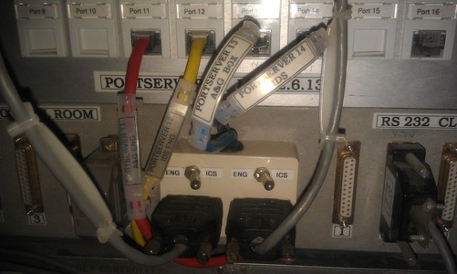
used. The RS232 connection runs to a panel mounted on the CASS
electronics
rack where control can be switched between two ports on a PORTSERVER,
port 13
which the ICS computer accesses over the network, or port 11 which a
Virtual PC accesses over the network for engineering use. This Virtual
PC is a Linux machine running on taurus with a dosbox
running the CDSAI Engineering software. The Virtual PC can be
accesed by starting a VNCViewer session on your computer, then connect
to: idsconsole:1 with the password: ******** A small box mounted on the panel fitted with
a switch selects to where the comms line is routed. See the picture below or Cassegrain
Interconnections drawing for more details.
n.b. Although only full I/O control with the Virtual PC is enabled with
the switch in the ENG position. When control is in the ICS position,
the Virtual PC can still read incoming data and will show if a mechanism
has moved. A useful diagnostic.
Here is an image of the Engineering software user interface:
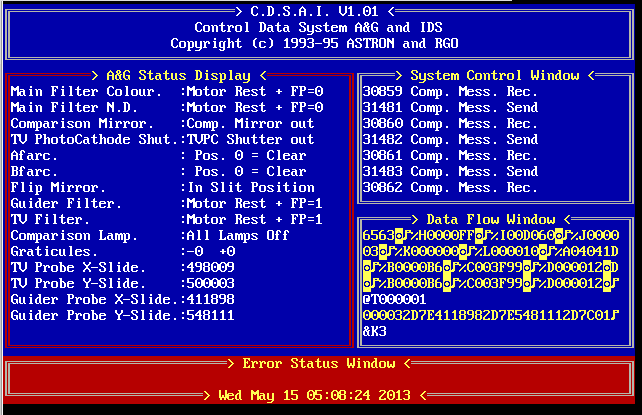
In case you see the DOS C: prompt instead of the above screen, you
can start the program by typing: cdsai <return>. If the screen is
present but not updating and no data scrolling then call someone from
the CFG group to restart the virtual machine idsconsole:1
(161.72.36.158). If the screen is present but the Error Status Window
says that there is no respons and there is no data scrolling in
the Data Flow Window, the instrument is switched off. This can be
switched on remotely by entering the INT Cass APC webserver.
The original instructions on howto operate the instrument with the CDSAI program can be found here , this document is a scanned version in pdf format, as the original document was lost.
References:
- Instructions on the CDSAI program, this document is a scanned version in pdf format, as the original document was lost.
- The IDS technical drawings have been digitised, organised and put onto the BSCW server.
- Document describing differences of the various SMD and XEA cards
- Document decribing the initial study by John Mills on the SMD cards
- Refer to the INT Technical Manuals, nos: 41
42 43 44 for full details and circuit drawings
for the A&G box.
- Refer to the INT Technical Manuals: 54
and 55 for the circuit drawings for MMS boards.
Last updated: 29 Oct 2020 rjp