The Seeing Trace Window
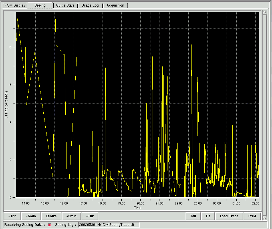
The seeing trace displays in real time, seeing estimates
provided by the NAOMI system. There are two plots, the first in yellow is used to indicate the estimated corrected
seeing and is an indication of how well NAOMI is performing. The second
trace in red is used
to indicate the natural uncorrected seeing . In the
case of the WFS control loop being in an open state, the observer can expect
to see both of the traces overlaying one another.
By default, the seeing trace file that is used as the source of
the information displayed, is updated every ten seconds. The display will
update in real-time as new seeing information is added to this file.
A new seeing trace file is created daily at midday and the name of the current
trace file is displayed in a small status panel located just underneath the
main seeing trace.
The seeing trace is flanked on two sides by a horizontal
and vertical scroll bar. If the seeing trace is displaying a
window onto the seeing data, these scroll bars will become active
and the observer may use them to scroll backwards and forwards
throughout the seeing information. If the observer uses the horizontal
scroll bar to position the seeing trace such that the latest seeing information
is displayed on the far right of the display, the display will automatically
scroll left as the latest seeing data arrives and the new seeing data
is plotted on the far right of the display.
The seeing trace display provides a mechanism through which the user
can magnify a particular part of the currently displayed trace. This
may be accomplished by pressing the left mouse button and then moving
the mouse cursor to the extent of the region that the observer wishes to
magnify. A dashed white rectangular line will be displayed on the window in
order to provide a visual clue to the current extent of the proposed magnification.
Once the user has moved the mouse cursor to the extent of the area to magnified,
if he then presses the left mouse button again, the area of the
trace enclosed by the dash white rectangular line will be magnified
to occupy the whole of the trace window.
It is possible to perform nested zoom operations, the level to which
the magnification feature has been applied will be displayed in the
top left corner of the seeing trace.
In order to cancel a magnification operation, the observer should
press the right mouse button whilst the cursor is positioned over
the seeing trace window. The effect of this will be to cancel the magnification
or in the case of a nested zoom, remove one layer of magnification.
The Time Window Modifier
Buttons
Located under the seeing trace display window is a series of buttons
which can be used to modify the time window of the seeing data that is displayed
by the seeing trace window.

Seeing Performance Time Window Modifier Buttons
The button labelled -1hr is used
to reduce the time window of the data that is displayed by the seeing
trace by a factor of one hour.
The button labelled +1hr is used
to increase the time window of the data that is displayed by the seeing
trace by a factor of one hour.
The button labelled -5min is used
to reduce the time window of the data that is displayed by the seeing
trace by a factor 5 minutes.
The button labelled +5min is used
to increase the time window of the data that is displayed by the seeing
trace by a factor of 5 minutes.
The button labelled Tail is used
to modify the seeing trace such that at it's maximum, the last 30 minutes
of seeing data will be displayed. If there is less than 30 minutes
of seeing trace data available in the seeing trace file then the seeing
data will be displayed in it's entirety in the seeing trace window.
The seeing trace window will automatically scroll as new seeing data becomes
available.
The button labelled Fit
will be used to instruct the seeing trace window to display
all of the available seeing data.
The Load Trace Facility
The system by default produces a new seeing trace file every day at
midday. The files are stored by default in the directory /wht/var/seeingLogs
. The application provides the user with the option of loading one of
the old seeing trace files into the performance meter so it is possible
to review the seeing from a previous night's observing. This can be accomplished
by pressing the button labelled Load Trace
which is located in the above button frame. The following dialogue window
will be displayed from where the observer can select a seeing trace file
from a previous night.
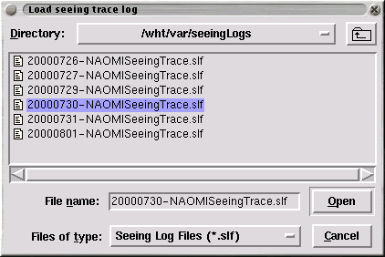
The Load Trace File Dialogue
The observer should highlight the file he wishes to load by clicking
upon it with the left mouse button and then pressing the Open button. Alternatively, the operation can
be abandoned by pressing the Cancel
button.
The Print Facility
The observer can print the seeing data which is currently displayed
within the seeing window to a nominated printer. This can be accomplished
by pressing the button labelled Print . The following dialogue
will be displayed within which the user can enter the name of the printer
that he wishes to print the seeing trace upon.
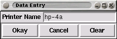
The Printer Dialogue
Once the name of the printer has been entered, the button labelled Okay should be pressed to initiate the print.
To cancel the operation, the observer can press the button labelled
Cancel .
The Performance Meter
Status Bar
Located at the foot of the performance meter sub-window is the performance
meter status bar. This status bar displays a number of different status.
The panel is used to display whether the performance meter is receiving
seeing data If no seeing data is entered into the seeing trace file for more
than 30 seconds, the small box to the right of the Receiving Seeing Data label will be coloured
red. If data is being received, the box will be coloured green.
The name of the seeing trace file that is currently being monitored is
also displayed in the performance meter status bar.

Performance Meter Status Bar
The Guide Star Selector Page
The purpose of the Guide Star Selector Page is to allow the observer
to load into the application, a list of science objects and corresponding
guide stars. Subsequently he will then be able to select
a guide star and offset the WFS probe such that when the science
object is located at the centre of the FOV, the guide star
will be positioned upon the WFS probe.
The page can be selected by clicking on the tab labelled
Guide Stars in the notebook tab area
(see above).
Once selected, the Guide Star Selector will be displayed in the
main work area as follows.
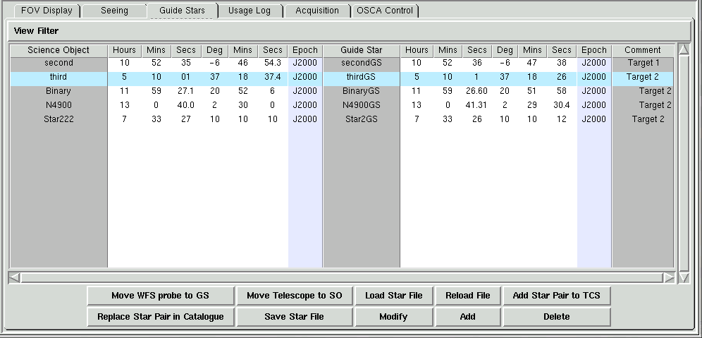
The Guide Star Selector Page
The guide star selector is divided up into a number of none editable
columns which are used to display the details of the science object-guide
star pairs. The columns describe the position of both objects in
RA and Dec and the user annotated name of the two objects.
In the final column is listed an optional comment associated
with the object pair.
The Add Star Pair To TCS
Facility
After first selecting a science and guide star pair in the guide star
selector dialogue by clicking upon it, it is possible to then add the coordinates
of the science object and the guide star to the TCS catalogue by pressing
the button which is labelled Add Star Pair to TCS
. This will result in the TCS being informed to insert an entry into it's
catalogue with the corresponding name. It then should be possible from the
TCS control terminal to simply enter gocat <name of science object>
in order to instruct the TCS to move to either of the new added positions.
The Replace Star Pair in Catalogue
This button provides the same functionality as the Add Star Pair to TCS button with the
difference that it will replace the exisiting star pair in
the TCS catalogue. If the star pair do NOT already exist in the TCS
catalogue then the TCS will return an error as the NAOMI GUI must first instruct
the TCS to remove the existing targets from the catalogue first before re-inserting
them.
The Move Telescope To
Science Object Facility
The intended purpose of the functionality associated with this button
is to facilitate the acquisition of a guide star and subsequent observation
of a faint object. By pressing this button the software will initiate a
blind offset of the telescope from it's current position such that
it is offset to the science object coordinates highlighted in the guide star
selector. Before doing this, the observer should have positioned the telescope
on the guide star and acquired the guide star using the WFS pickoff probe.
The software will ensure that the WFS pick off probe remains positioned over
the guide star whilst the telescope is being offset.
Prior to performing this operation, the system will ensure that the
AO loop has been opened and will warn to the contrary. This is to prevent
any disturbance to the AO system caused by the offset of the telescope.
The loop should then be closed again once the offset is complete.
The Load Star File
Facility
Prior to being able to use the guide star selector window, the
user must load a suitably prepared guide star file
which details a list of science object-guide star pairs in a pre-defined
format. This can be accomplished by pressing the button labelled Load Guide Star File which
is located at the foot of the guide star selector
window. The guide star file can either have been prepared by hand or
using the Star Position Data
Editor .
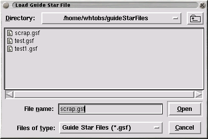
The Load Guide Star File Dialogue
By default, the guide star files are expected to have the suffix
.gsf appended to them so as to distinguish them from other files that
may be present in the directory. The file selector window will by default
only display files in the guide star file directory /home/whtobs/guideStarFiles
which have the .gsf suffix attached. The
user must click upon one of the files listed in the dialogue using the left
mouse button and then press the Open button in order to load the file.
The expected format of the guide star files is detailed in the
next section
.
If the user wants to cancel the dialogue without any action, the user
should press the button labelled Cancel .
Once a file has been selected, the application
will then check the file for consistency and report any errors back to the
observer. If any errors are detected, the current guide star list will remain
unchanged.
Format of the Guide Star Files
The format of the guide star files is expected to consist of
lines of ASCII text lines adhering to the convention in the following
table. Each field is mandatory except for the comment field,
and must be delimited by a space character.
| Science Object Name |
HH |
MM |
SS |
DD |
MM |
SS |
Epoch |
Optional
Comment |
| Character string with no spaces |
0 .. 23 |
0 .. 59 |
0.0 .. 59.999 |
-90 .. 90 |
0 .. 59 |
0.0 .. 59.9999 |
J2000 |
! <text> |
The lines in the file should alternate between science objects
and their corresponding guide star. If there is a case where there
is a science object with more than one guide star, the user should
still ensure that each guide star is preceeded by the name of the
science object to which it is associated despite the redundancy.
The user should not use preceeding zeros on numbers.
Following is an example of a guide star file.
BrightStar
10 9 8 -60 20 20 J2000! A bright star
BrightStarGS
10 9 8 -60 20 20.2 J2000
LessBrightStar
23 9 8 -60 22 20 J2000! A less bright star
LessBrightStarGS 23 9 8 -60
22 21.9 J2000
The Reload Star File Facility
The button labelled Reload Guide Star File may be used to reload the last guide star
file that was loaded. This is useful in the case that the user may want to
add more guide stars to the guide star file and this provides a quick method
to reload the guide star file once it is modified.
The Modify Star Position Facility
By pressing the button labelled Modify
the user can edit the position of
a currently selected star pair. First the user must click on the star
pair that he wishes to edit such that it is highlighted and then press the
Modify button. Once pressed, the Star Position Edit dialogue
window will be displayed with the fields prefilled with the selected star
position data.
The Add Star Position Facility
The user may add a new star pair by pressing the button labelled
Add. This will result in the Star Position Edit
dialogue window being displayed. The user can then fill in the star
position fields present in the form. By clicking on the button labelled Update Entry, the new star position data that
was entered will be verified for correctness and subsequently added
to the guide star list.
The Delete Star Position Facility
By pressing the button labelled Delete
in the guide star page, the user can delete the currently
selected star position in the guide star list.
The Save Guide Star List Facility
By pressing the button labelled Save Star
File, the user can save the details of the star positions which
are currently displayed in the list.
The Star Position Edit
Window
This dialogue window will allow the user to either modify the position
data of an existing pair of stars in the guide star list or to add a completely
new pair of stars to the list. The dialogue will be presented whenever the
user presses the Add or Modify buttons on the guide star page.
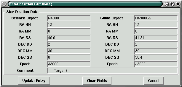 The Star Position Edit Dialogue
By pressing the Modify button on the
guide star page, the user can edit the data associated with the currently
selected star position in the guide star list. The fields in the form
will be pre-filled with the position data associated with the entry that
was selected in the guide star list.
When the user presses the Add button on the guide star page, the dialogue
will be presented with all of the fields empty ready for the user to enter
a completely new set of star positions.
The user must fill the fields in accordance with the guidelines outlined
in the section relating
to the format of guide star files. Once all of the fields have been
correctly filled, the user can update the guide star list by pressing the
button labelled Update Entry.
By pressing the the Clear Fields button,
all of the fields in the form will be cleared.
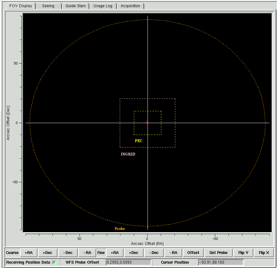
Offsetting the WFS Probe onto the Guide Star
Once a guide star file has been loaded into the
guide star selector, the observer may then select guide stars
from the list and offset the WFS probe. This can be done by clicking upon
any of the entries in the guide star list using the left mouse button and
then pressing the button in the bottom left of the sub-page labelled Move WFS Probe to Guide Star.
A prerequisite to being able to offset the WFS
probe is that the WFS control loop must be open.
The user should be able to monitor the progress
of the movement of the probe by switching to the FOV Display
The Usage Monitor
The purpose of the Usage Monitor is to provide a wide variety
of status information about operation of the application. The information
is more applicable to the engineer than the observer. It details commands
which have been sent to the NAOMI hardware as well as other information pertaining
to the execution of the application.
The Usage Monitor Page can be selected by clicking on the
tab labelled Usage in the notebook tab
area (see above).
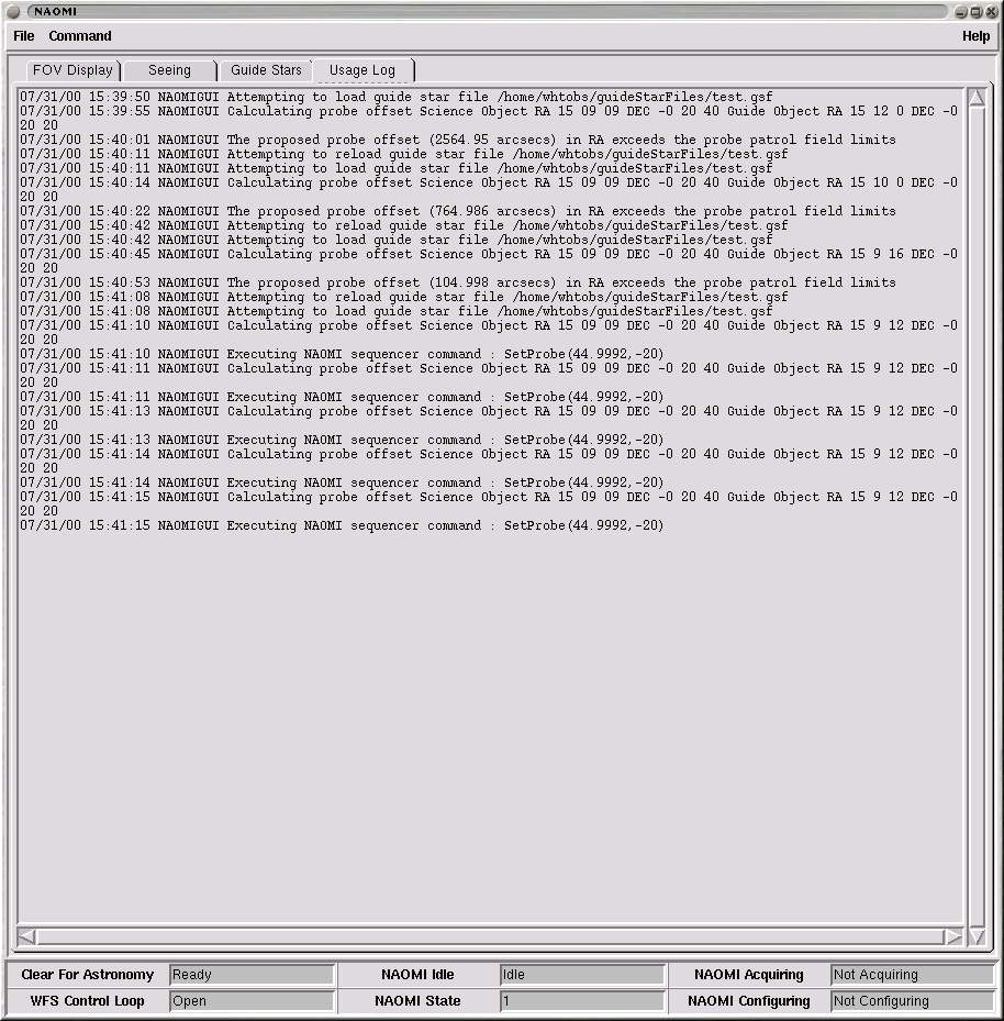
The Usage Monitor
OSCA Control Panel
The OSCA control panel can be used by the observer to control the various
mechanisms associated with NAOMI's coronagraph, OSCA. The control page can
be selected by the user by clicking on the tab labelled OSCA Control
at the top of the window. The OSCA control panel looks as follows;
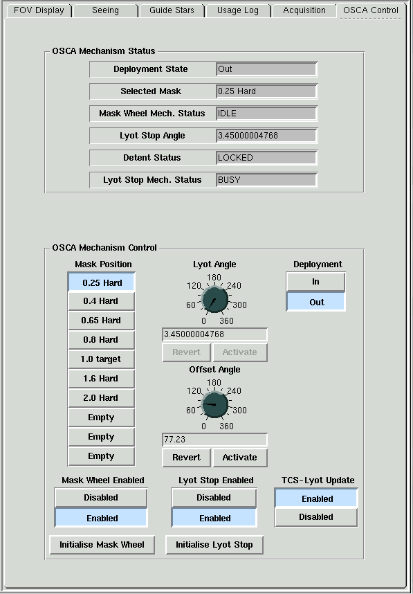 OSCA Control Panel
The OSCA Status Panel
The OSCA status panel displays various status information relating to the
OSCA EPICS VME system. This information is updated in real-time as status
parameters change within the EPICS system.
A summary of the displayed status values follows;
- The Deployment Status of the instrument reports whether
or not OSCA is deployed into the lightpath. The status should report either
In to signify that OSCA is in the lightpath and Out to
signify that OSCA is not in the lightpath.
- The Selected Mask indicates the currently selected mask
which is being reported by the EPICS system.
- The Mask Wheel Mech. Stat indicates what the
activity status of the mask wheel mechanism is. This can be one of
Busy , Disabled, Init, Undefined or Idle
.
- The Lyot Stop Angle status indicates the current rotation
angle in degrees of the lyot stop mechanism as reported by the EPICS system.
- The Detent Pin status indicates the current position of
the mask wheel detent pin and be either Undefined, Locked
or Unlocked.
- The Lyot Stop Mech. Status indicates the current movement
status of the lyot stop mechanism and can be one of the following values;
Busy, Disabled, Init, Undefined
or Idle.
The OSCA Mechanism Control
Panel
The OSCA mechanism control panel is located at the foot of the OSCA control
page and can be used by the user to control the mask wheel, deployment and
lyot stop mechanisms. The controls on the panels are described in the following
sections.
It should be noted that whilst
any of the mechanisms are moving,
controls on the display which are specific to that mechanism will remain
disabled to user control.
The Mask Position Control
The control consists of 10 buttons stacked vertically labelled with each
of the masks which can be found in the positions on the mask wheel. The user
can request a mask position by simply clicking on the corresponding mask button.
Should the mechanism be in an error state, disabled or moving, this control
will be disabled.
The Mask Wheel Enabled
Control
The low level EPICS system allows two states for the mask wheel mechanism,
enabled and
disabled. When the mechanism is in the
disabled
state, the OSCA EPICS system will forbid any requests for movement of the
mechanism. The user can toggle the system between the two modes by clicking
on the
enabled or
disabled buttons. It should be noted that
when the OSCA low level EPICS system is requested to
enable the mechanism,
it performs an initialisation of the mechanism which takes a short amount
of time to perform.
The Initialise Mask
Wheel Control
The button labelled
Initialise Mask Wheel can be used to initialise
the mask wheel mechanism. This action will take a short period of time to
perform and the application will request user confirmation prior to performing
the action.
The Lyot Angle Dial Control
The lyot angle dial control can be used to manually set the angle of the
lyot stop mechanism. In order to specify the value, the user can either turn
the dial until the desired angle is reached or edit the value in the entry
field located directly below the dial. Anytime the value displayed differs
from the value of the actual mechanism, the text in the entry field will be
shown in red.
By clicking on the button labelled
Activate, the OSCA EPICS system
will be requested to move the mechanism during which time the control will
be disabled. Once the mechanism has reached it's demand position, the control
will become enabled once again.
It should be noted that whilst the mechanism is disabled, in an error state
or moving, the control dial will remain disabled.
The button labelled
revert can be used to instruct the dial to re-read
the current value of the lyot angle. This is useful after the user has modified
the value in the control but decides to abandon his change request.
While the Lyot Stop Rotation Angle Update daemon is running, the user will
find that this mechanism is updated every couple of seconds and therefore
in order to disable this, he should refer to the section on
enabling and disabling the rotation
angle update.
The Lyot Offset Angle
The lyot offset angle dial control can be used by the user to manually
set the lyot stop offset angle which is used in the calculation which sets
the angle of the lyot stop mechanism when the position of the derotator angle
on the telescope changes. This angle should
only be changed by
trained staff and performed after engineering work on OSCA when the
position of the instrument has been changed. The angle is permanently stored
in the WHT ICS database and is thus preserved across restarts of the system.
Valid values for this angle are in the range 0 to 360 degrees expressed as
a real number.
The angle can be modified by the user by either
turning the
dial until the desired angle is reached or editing the value in the entry
field located directly below the dial. Anytime the value displayed differs
from the value of the actual mechanism, the text in the entry field will be
shown in
red.
By pressing the button labelled
Activate, the
Lyot Stop Update
Daemon will be informed of the new value and subsequent automatic calculations
of the lyot stop rotation angle will be calculated based on the new offset
value.
The Lyot Stop Enabled Control
The low level EPICS system allows two states for the lyot stop mechanism,
enabled and
disabled. When the mechanism is in the
disabled
state, the OSCA EPICS system will forbid any requests for movement of
the mechanism. The user can toggle the system between the two modes
by clicking on the
enabled or
disabled buttons. It should be
noted that when the OSCA low level EPICS system is requested to
enable
the mechanism, it performs an initialisation of the mechanism which can
take about
6 minutes to perform.
The Initialise Lyot Stop
Control
The button labelled
Initialise Lyot Stop can be used to initialise
the lyot stop mechanism. It should be noted that this action can take almost
6 minutes to perform and cannot be interrupted once started.
The OSCA Deployment Control
The OSCA deployment control can be used to deploy OSCA into the lightpath.
The user can deploy OSCA by pressing the button labelled
In and remove
OSCA from the light path by pressing the button labelled
Out.
The TCS-Lyot Update Control
This control reflects the current status of the Lyot Stop Update daemon
and whether or not it is automatically updating the position of the rotation
angle when the derotator angle on the telescope changes. This can be either
enabled or
disabled by pressing the corresponding button.
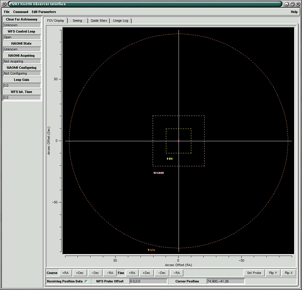
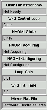
The NAOMI Status Panel
Displayed at the foot of the application window is the NAOMI Status
Bar which displays various status information pertaining
to the general state of the NAOMI system. The status panel looks as follows;
The NAOMI Status Bar
The field labelled Clear For Astronomy is used to indicate to the observer that the NAOMI system
is ready for astronomy. If this is the case, the value of this field
will be ready. This status is an indication that there are no alignment
or acquisition beamsplitters in the optical path, that the WFS is focussed
and that the WFS integration time is within the nominal range. It is a check
that some acquisition or alignment feature of the NAOMI opto-mechanical or
control systems has not been left in a state inappropriate for observation
The field labelled WFS Control Loop is used
to indicate the current state of the WFS control loop and whether it is
open or closed.
The field labelled NAOMI Idle is used to indicate
whether NAOMI is in such a state where it is not acquiring and
not configuring and that
the control loops are open
. If all of these three conditions are true, the value of this status
field will be set to idle otherwise it will be set to busy
.
The field labelled NAOMI State is used to
indicate the current state of health of the NAOMI system. If NAOMI is in
good health, this field should indicate Okay. If this field is signifying
an error condition then it will be necessary for a NAOMI error reset to be performed
The field labelled NAOMI Acquiring is used
to indicate that the WFS integration time has been lengthened and that
either the PEC (Pre-correction camera) or WFS doublet (turns the
WFS into an acquisition camera) has been deployed so that a guide star
can be acquired onto the WFS probe. The value of this field will be either
Acquiring or Not Acquiring depending
on the state of the system.
The field labelled NAOMI Configuring is used
to indicate whether any of NAOMI's mechanisms are in motion or some software
configuration is in progress.
The field labelled Loop Gain
is used to display the current AO loop gain.
This is expressed as a real where 0.0 is the minimum and 1.0 is the maximum.
The field labelled WFS Int. Time is used to
display the current integration time of the WFS camera. This time is expressed
in milliseconds.
The field labelled Mirror Flat File is used to display the name
of the last mirror flat file that was loaded using the NAOMI top level GUI.
If there is a case when the NAOMI status bar
is unable to communicate with the NAOMI control system in order to
establish status, all of the status fields will be flagged as follows to indicate
no status is available.
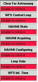
Bad NAOMI Status
If this occurs, the engineer should check that the EPMDataServer
is running correctly on navis.ing.iac.es and that the NAOMI
control system is operating correctly.
Observer Prepared Command
Scripts
A number of command line driven scripts are available which can be incorporated
into observer prepared observation scripts. These scripts provide
the observer with the ability to control the NAOMI hardware as well as perform
dithered observations using an NAOMI/INGRID/UltraDAS based observing system.
The following scripts are available
The loop Command
The loop command allows the observer
to open and close the WFS control loop from the command
line or from a command script.
The dither Command
The dither command allows the observer
to perform dithered observations.
The positionWFSprobe
Command
The positionWFSprobe command
allows the observer to offset the WFS probe from centre of the probe
patrol field to the expected position of a guide star.
The naomireset Command
The naomireset command allows the
observer to reset any NAOMI errors that might currently be reported
by the NAOMI system from the command line.
The Packet Collection Task
The packet collection task
will be used to collect headers which will be served to UltraDAS after
data acquisition in order for it to complete the creation of it's FITS files.
The application is DRAMA based and can be used to extract headers from
both EPICS based systems and the python based NAOMI system with it's Electra
Process Monitor. More detailed information relating to this application
can be accessed by clicking here .
The Seeing Logger Task
The seeing logger task is used
to generate the seeing trace files which are displayed by the seeing performance meter
found in the main NAOMI GUI. The manual page associated
with this application can be found by clicking here.
EPM Data Server
The Electra Process Monitor Data Server
is an application that acts as a bridge between any
application that the observer might use to control and monitor NAOMI and
the NAOMI system itself. This application must be running in
order prior to any of the other applications outlined in this document
being used. Click here
to access more information about the EPM data server.
OCS-EPM Bridge Server
The OCSEPMBridge is a daemon
process running upon taurus. It's purpose is to transfer parameters from
DRAMA and EPICS based systems into the NAOMI Electra Process Monitor. The
daemon is configurable in the parameters which are conveyed between the
systems. There is one instance of this daemon running on taurus and the
purpose of the task is to transfer the information from the TCS DRAMA task
TELD to the NAOMI system so that NAOMI can set it's ADC accordingly.
Starting and Stopping the NAOMI Observer Software
The naomi script can be initiated from
the command line and permits the NAOMI top level observer software to be
started or stopped. Normally the execution of this script will be incorporated
into a higher level script that starts and stops the observing system and
should not be used by the casual user. For more information click here