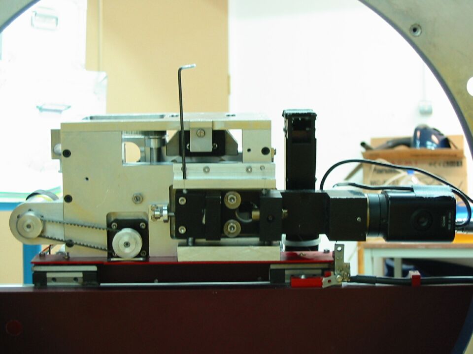
Alignment fibre view system and rotation of the theta bearing.
If the camera has been removed from the gripper unit is will be necessary to check that the centre on the camera coincides with the centre off rotation of the theta axis. Further it is important that the camera is not rotated in relation to the X and Y axis this will be explained in camera orthogonality
Centre of rotation.
This alignment can be done with the gripper taken off the rest of the robot. This makes things easier to adjust, since the adjusting screws are on the bottom off the gripper which are inaccessible when the unit is fitted on the robot. A disadvantage is that we don't have the gripper cabled up and it's not possible to move the mechanisms using the engineering terminal.
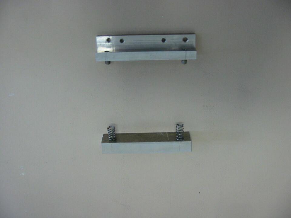
| With help of a spring block and an adjusterblock we can do this test with the gripper in place. The grubscrews are now accessible and the springs push the camera up. These are stored in the AF2 cabinet. | |
Aligning the gripper theta axis with the tv centre means that as a fibre is gripped in the jaws and the theta axis is rotated the fibre image should rotate around the tv centre.
Method: A dummy fibre is gripped in the jaws, slightly off axis with light shining down the bare end. The video output should be displayed on a live video tv screen. Then the Z-axis can be moved to focus the image (around 4000). Rotation off the theta axis then determines the axis off rotation. The image should move around (because its slightly offset) a centre point on the screen.
Start rotating the fibre between cardinal points: fibre 1/41/81/121
Go to extended mode to move Z and Theta.
Put fibre slighly offsett in the gripper jaws.
Close gripper jaws (gripper closed)
Check on Tv that fibre is visible
Draw a cross in the centre of the screen: draw two lines from the corners of the screen that intersect in the centre of the screen.
Now type tmove 0
Draw with marker fibre image on screen
Tmove 5400 (fibre 41) and draw image
Tmove 10800 (fibre 81) " " "
Tmove 16200 (fibre 121) " "
Now check that the centre of the 4 cardinal fibres coincide with the centre on the screen
If the centre of rotation is the same as the centre on the screen you can be sure that the tv is properly aligned.
If the centre is offset, you have to adjust the camera.
Put the springblock in place and bolt on the adjusterblock photo
Take off the tape to reach the two allen bolts
Carefully loosen the bolts
Use the two grubscrews (vertical movement) to move the image from left to right and the allenbolt on the left side (horizontal adjustment) to move vertical (left to right on the camera assembly is top to bottom on the Tv screen)
This will take probably a couple off attemps, you will find that there's some crosstalk
An accurate way of determining the centrering, is to measure the distance from each image to the centre of the tv monitor.
Important: try to get the necessary adjustments by only moving in X and Y direction and not by introducing a rotation! If the cameratube assembly drops down to far there's the risk of collision with the zeroset optoswitch.
Finally take away the two blocks and store them in the AF2 cabinet.
After this is done there's one more test to be done on this mechanism: Camera orthogonality.
Camera orthogonality.
It is important that the camera is orthogonal with the X and Y axis. With the optics in the system it is possible to align it so that it seems that the centre of rotation coincide but in reality your introducing another error. This is check in the following way:
Another way of doing it is using the testgrid. Bolt on the testgrid and move the robot to 0,0 which should see the central dot. NB the Z position should be 0 whenever the test grid is in place. Offset the robot in X and measure the diplacement on the tv screen in y. The pulnix camera should be carefully rotated to minimise any change in y for a movement in x.
Last updated 1st Apr 2011 by Renee Pit