WYFFOS/PFIP REDPLUS4 Commissioning Report
Final Report 22 Dec 2014
Completed by Lilian Dominguez and Andy Ridings
Based on a template provided Andy Ridings and Steve Smartt (Feb 2000)
Master document available here:
/data/docs/Astronomy/instruments/af2/WYFFOS-REDPLUS4/WYFFOS-REDPLUS4-COMMISSIONING-REPORT.htm
accessible via
http://www.ing.iac.es/astronomy/instruments/af2/WYFFOS-REDPLUS4/WYFFOS-REDPLUS4-COMMISSIONING-REPORT.htm
1 Introduction
1.0 Status
The report is complete. Automatic QC to be commissioned.
1.1 Purpose
This document describes the ING test requirements for the commissioning and acceptance of all new CCDs. As the generic test plan, some tests may not be relevant to a new detector on a particular telescope or focal station. This may be noted in any such test.
1.2 Scope
The tests can be divided into two broad categories:
1. Functional tests - designed to verify and validate the functional behaviour of the CCD within the Data Acquisition System.
2. Acceptance tests - tests designed to verify that the package is acceptable to the ING commissioning astronomer.
The functional and acceptance test will be carried out at the direction of the ING commissioning astronomer, although it is not expected that they will themselves carry out all the tests.
The test results will be fully documented, both in the condensed form of the CCD characteristics data sheet, and in the full form of the completed test plan to be held by the detector group.
Both the functional tests and the acceptance tests might be applicable to
the testing of any subsequent modifications to the CCD and it's software -
when only the relevant sections need to be carried out.
1.3 References
1. TEK4 Commissioning tests, RGMR.
2. TEK on INT/JKT - Testing, and Acceptance, PMF.
3. CCD Commissioning, DRM.
4. Red+2 on INT/IDS Commissioning tests, OVIDIUV
1.4 Overview
In the following sections the functional and acceptance tests are described in detail. Please see the above links (under the title) where the master document, figures, plots and all FITS data reside.
When carrying out the tests in the following, sections, the run numbers of
any frames (and dates) evaluated should be recorded for future reference in
the ING archive and printouts of relevant images stored with the commissioning
file.
2 Functional Tests
2.1 Mechanical arrangement
MechU001 The cryostat should accept filler tubes of different lengths
and be filled with liquid nitrogen and cooled.
| Notes: The tube fits and seals correctly. The autofill system has also been fitted and functions correctly.
|
MechU002 LN2 filler tube location should allow LN2 to remain in the
cryostat at all telescope positions. Put appropriate filler tube in and attach
CCD to its nominal focus on the telescope.
| Notes: Wyffos is stationary, PFIP does not use a filler tube. |
MechU003 The filler tube length needed for each of the various instruments
that the device will be used on, should be recorded here.
| Instrument | Tube Length |
| WYFFOS | Long |
| PFIP | None |
| Notes:
|
MechU004 Capstans should have clamps on and with these clamps tight,
the capstans should have no movement - both rotationally, and in slop.
| Notes: Clamps are fitted and functional |
MechU005 Establish the position of the CCD surface relative to the
window front face. and relative to the cryostat (metal) front face, and record
them here.
| Notes: 10 mm
|
MechU006 The cryostat should physically fit all the instruments it
could ever be used with. Note down here the instruments that have been tested.
| Instrument | Tested |
| WYFFOS | ok |
| PFIP | ok |
| Notes: |
MechU007 The flatness of the chip itself should be known. This should
have been measured before delivery to ING. Check that there is no gross curvature
across the chip by either FWHM measurements of stellar profiles (if chip
is to be used for imaging) or through Hartmann shifts (or FWHM estimates
of arc lines if chip is to be primarily used for spectroscopy). Note down the
method used and the approximate shape of any curvature.
| Notes: 5 microns peak to valley (E2V) |
MechU008 Flexure of the CCD relative to the sky should be noted for
the most common focus for the detector. A full flexure test is not necessary
for full commissioning, but the flexure between zenith and ~60 degrees from
zenith should be noted and compared with what is expected. Advice from the
appropriate instrument specialist can be sought.
| Notes:
When used at WYFFOS the CCD remains fixed on position independently of the telescope position. Hence this test is not applicable. |
MechU009 It should not be possible for the radiation shield inside
the cryostat to impinge on the light path, for any, of the likely foci that
the detector may be used. Indicate here that this has been checked and is
acceptable.
| Notes: Checked ok
|
2.2 CCD performance
PerfU001 The number of the controller used for the performance tests
should be noted.
| Notes: Redplus4 'B' |
PerfU002 The .lod file used for this detector should be recorded here.
| Notes: timGen3.RED+4.2013-05-08.lod |
PerfU003 The DAS system should be able to start up and prepare for
reading out the CCD. Start up the instrument control system, with the detector
under test in use note down any errors or warnings.
| Notes: The system starts correctly. |
PerfU004 The bias readout time is needed for each readout speed.
'Using "BIAS" until the prompt returns, or until the system indicates that
the run has completed. Leave blank any unsupported readout speeds. Note
which DAS system was in use for this test.
| |
Bias readout time (sec) |
| slow | bin 1x1: 51 bin 2x2: 18.5 |
| fast | bin 1x1: 40 bin 2x2: 15 |
| Notes: No windowing was done. The above measurements are the total times to read the whole CCD. |
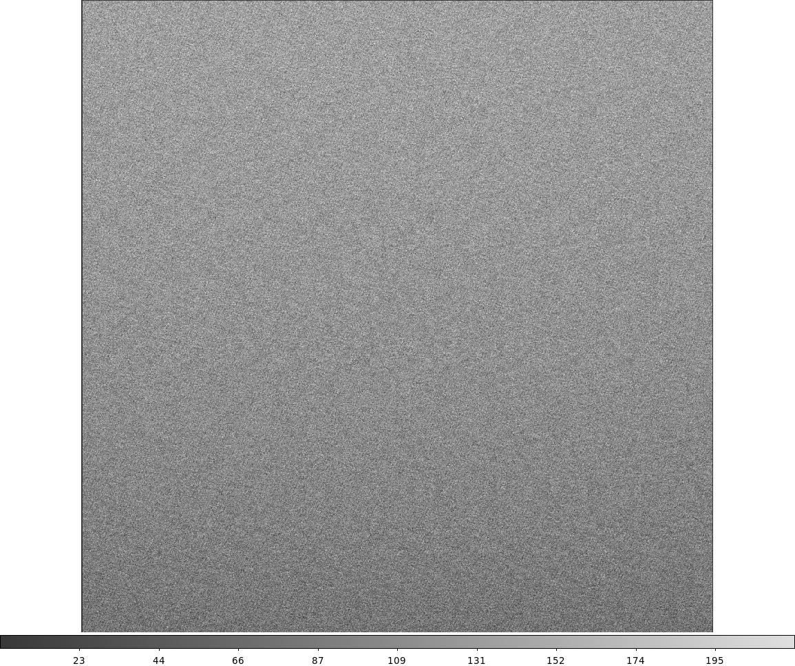
PerfU005 The bias, level and readout noise in ADUs should be measured,
with all lights off and curtain shut - preferably at night. Take 2 bias
frames at all available readout speeds. Using ING analysis scripts or any
other means measure the bias level and readout noise in ADU. Note these
down for all supported speeds. Keep the runs used.
| |
Binning | Bias Level (ADU) | STDDEV (ADU) | Readout noise (e) |
| slow | bin 1x1 bin 2x2 |
3205 3432 |
6.5 - 7.8 6.1 |
4.5-5.5 4.2 |
| fast | bin 1x1 bin 2x2 |
1240 1508 |
6.1 6.1 |
6.1 6.1 |
| Notes: Run numbers of biases used for the above measurements: 1916436-1916446, 1916538-48,1916979-89, 1917052-62. The measurements were performed with the IRAF task "imstat" Readout noise (e-) calculated by multiplying STDDEV (ADU) by the gain (0.69 e-/ADU for slow and 1.0 e-/ADU for fast, acc to RED+4 tech specs). |
PerfU006 Gain should be measured using the ING analysis scripts
(or the IRAF script ccd_gain). Note down the gain and the electron readout
noise at all supported readout speeds. Write down the archived run numbers if applicable.
| |
|
|
|
| slow | bin 1x1 bin 2x2 |
0.73 0.70 |
4.51 4.05 |
| fast | bin 1x1 bin 2x2 |
1.10 1.04 |
4.96 4.59 |
| Notes:
The IRAF task "findgain" was used to measure the gain and readnoise. Two
pairs of flats and biases were used, as inputs, for each CCD configuration. |
PerfU007 Bias structure needs to be checked. This is most clear
on a MULTBIAS 10 or on 10 bias frames combined. This should be done at night
to reduce the effect of light leakage. If it is not done at night ensure
that any structure is not a light leak. It should be done for each speed
at which it will be used in science mode (ie standard, quick and turbo)
note down run numbers and dates.
| Notes:
BIN 1x1 SLOW: BIN 2x2 SLOW: BIN 1x1 FAST: BIN 2x2 FAST: The run number of the bias frames used to check the bias structure are: r1916454-64, r1916465-75, r1917074-82, r1917063-73
|
PerfU008 Any variation in bias structure should be noted. Take a
bias frame whilst the telescope is tracking, derotating and autoguiding
and with other sources of RF interference that are possible. Note down the
conditions and the readout noise for this test, and any "banding" apparent
on the frame. Note the run numbers.
| |
Readout Speed | Binning | Bias Level (ADU) | STDDEV (ADU) | Readout noise (e) |
| Stopped | slow | bin 1x1 bin 2x2 |
3191 3426 |
5.8 - 6.4 5.4-6.3 |
4.5-5.5 3.7-4.3 |
| | fast | bin 1x1 bin 2x2 |
1234 1505 |
5.7-5.9 4.3-5.0 |
5.7-5.9 4.3-5.0 |
| Guiding | slow | bin 1x1 bin 2x2 |
3191 3426 |
6.1 - 6.6 5.2-6.3 |
4.2 - 4.5 3.6-4.3 |
| | fast | bin 1x1 bin 2x2 |
1234 1505 |
5.7-5.9 4.4-4.8 |
5.7-5.9 4.4-4.8 |
| Tracking and derotating | slow | bin 1x1 bin 2x2 |
3195 3426 |
5.8 - 6.9 5.2-6.3 |
4.0 - 4.8 3.6-4.3 |
| | fast | bin 1x1 bin 2x2 |
1236 |
5.8-5.9 |
5.8-5.9 |
| Notes: In the four CCD modes checked the bias level remains stable independently of the telescope being stopped, tracking or guiding.
However the noise seems to increase slightly when the telescope is tracking and/or derotating. Run numbers: stopped at zenith: r1909303-28, guiding: r1909167-86, tracking+derotating: r1909066-98 |
PerfU009 The linearity of the device should be known. Carry out
linearity tests at all supported readout speeds. Note the integration times
used, the resulting values. Draw a graph of the deviation from linear for
all readout speeds and attach the graphs to this document.
| Notes: Lamp flats were taken with exposure times in the range 0.2 - 35 sec, in the four CCD configurations below. To illuminate uniformly the CCD, a white lamp flat was placed inside WYFFOS. The count level values were measured over a small region of 200x200 pixels in the centre of the images. BIN 1x1 SLOW: BIN 1x1 FAST: BIN 2x2 SLOW: BIN 2x2 FAST: |
PerfU010-PerfU015 Binned readout mode. Carry out tests PerfU004-PerfU009
and note down the results when using the chip in 2x1, 1x2 and 2x2 mode.
| Notes: See above (PerfU004-PerfU009) the results and data for binning 2x2. No data were taken for binning 2x1, 1x2. |
PerfU016-PerfU021 Windowed readout mode. Carry out tests PerfUOO5-PerfU009
and note down the results when using the device is windowed. If the CCD
is to be used on a spectrograph were a particular window will generally
be used then this window setting should be used then this window setting
will be used for tests.
| Notes: No windowing is necessary when Red+4 is used with WYFFOS. Hence no tests were carried out with any especific window setting. |
PerfU022-27 If two-gain mode is available with this chip then the
tests Perf005-009 should be carried out with the more ‘uncommon’
setting. Do 2 x 900 sec dark exposures at night. Note down the dark current
and the run numbers used.
| Notes:
Run numbers: 3 dark frames of 900 sec (slow readout speed, binning 1x1): r1916549-51 |
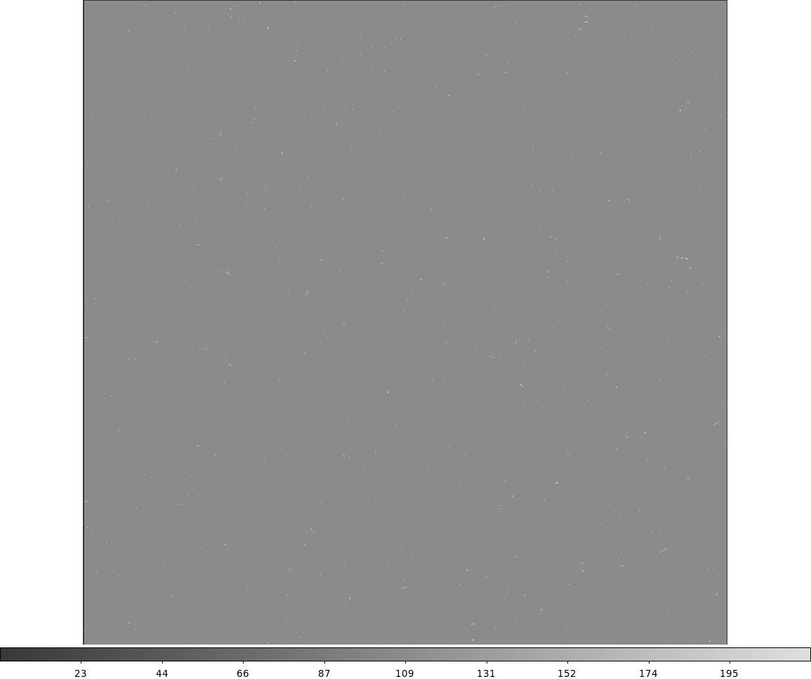
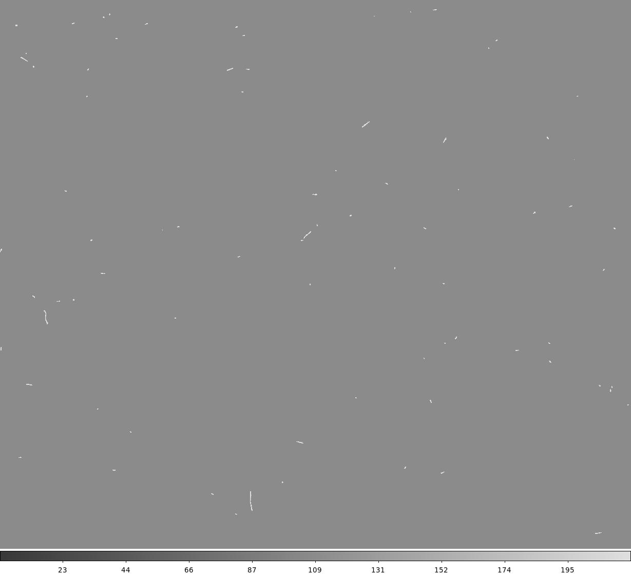
PerfU028 Using the above frame estimate the cosmic ray count, in
events per hour. The hot pixels intrinsic to the device can be found combining
the images within IRAF with appropriate clipping parameters.
| Notes:
The average cosmic ray events per hour is ~3300 in the whole detector area. |
PerfU029 Using the dark images taken in Perf028 produce a bad pixel
map and attach a printout of the image with the look up table optimised
to show the traps. List pixel co-ordinates of all traps and other poor cosmetics.
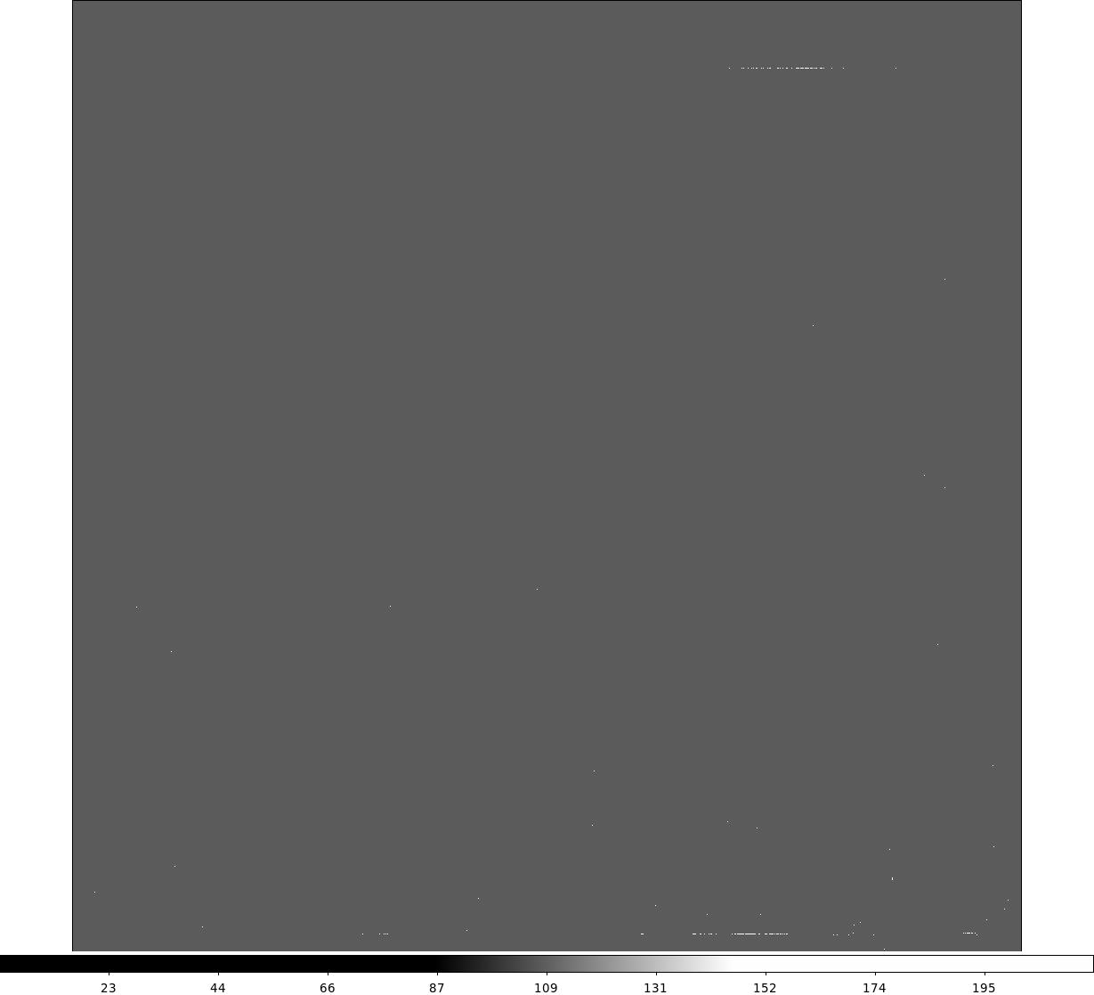
| Notes: Detector lamp flats (lamp inside WYFFOS spectrograph) were used, instead of dark frames, to produce bad pixel masks. High (~30,000 ADUs, r1916436-46) and low (8,000 ADUs, r1916401-04) level flat frames (slow readout, binning 1x1) were taken and then combined. Then the high master flat frame was divided by the low master flat. The resulting image was used to produce the bad pixel mask with the IRAF task "ccdmask". As main features, it is possible to see a row of bad pixels at the bottom of the CCD (y ~ 85 pix) and another bad pixel row at the top (y ~ 3810 pix). |
PerfU030 Take a flat field exposure (e.g. sky flat, lamp flat or
dome flat) and normalise the signal level to approximately unit. Attach
a copy of this image to show cosmetics and the pixel to pixel response variations
that cannot be seen in the dark images. Note the run number used.
| Notes: Flat field exposures were taken with a white lamp inside WYFFOS, no filters were used. The lamp did not illuminate homogeneously the detector, so these flats are not adequate to measure the pixel-to-pixel variations in the detector. Run numbers: r1916436-46 (slow readout, binning 1x1, ~30,000 ADUs). The individual flat frames were debiased and combined to produce a master flat frame. |
PerfU031 Calculate the pixel-to-pixel variations, using well exposed
multi-flats in PerfU032. Show how the calculation was done.
| Notes:
The lamp inside WYFFOS used for the flat frames did not illuminate homogeneously the detector, so these flats are not adequate to measure the pixel-to-pixel variations in the detector. |
PerfU032 List the charge transfer in all readout speeds (provided by manufacturer).
Include plots of cosmics and method of calculation.
| Readout Speed | HCTE | VCTE |
| slow | 0.999996 | >0.999998 |
| Notes:
See PerfU028 for counting cosmic ray events. |
PerfU033 The stability of the bias level and readout noise should be noted. The CCD-controller must itself have been powered up continuously for 24 hours, then without turning the drive box off, note down the bias level and readout noise (in ADUs) every 6 hours for 24 hours.
NB this should be done during the first S/D night when the chip or mosaic
is on the telescope.
| Notes: We measured the bias level and standard deviation several times during the three days of commissioning, at ~12hr intervals or less, for all CCD settings. The median number of counts (obtained with "imstat") show a very stable bias level (within a few count (< 10 ADUs) difference): |
| |
Binning | Bias Level (ADU) | STDDEV (ADU) | Readout noise (e) |
| slow | 1x1 |
3196 3202 3195 3192 3191 |
6.3 6.4 6.2 6.4 6.3 |
4.3 4.4 4.3 4.4 4.3 |
| 2x2 |
3424 3430 3434 3430 3431 3427 3425 |
5.9 5.7 5.8 5.7 6.2 5.8 6.2 |
4.1 3.9 4.0 3.9 4.3 4.0 4.3 |
|
| fast | 1x1 | 1237
1240 1236 1229 1228 |
5.9 6.0 5.9 5.9 6.3 |
5.9 6.0 5.9 5.9 6.3 |
| 2x2 | 1508
1511 1508 1505 1499 1500 |
4.5 4.4 4.5 4.6 4.4 4.5 |
4.5 4.4 4.5 4.6 4.4 4.5 |
2.3 Astronomical measurements and test
The astronomical tests to be carried out will depend on if the chip
is to be commissioned at a spectroscopic or imaging focal station. If spectroscopy
then skip to section 2.3.2 and leave this section 2.3.1 blank.
2.3.1 CCDs for use at imaging stations. (The camera is not to be commissioned at PFIP therefore this section does not apply.)
AstroImageU001 Find out where the optical field/rotator centre is
on the CCD. Adjust to silicon centre if possible. Note down pixel coordinates,
the instrument name and any telescope and capstan settings that effect this.
| Notes: N/A |
AstroimageU002 Align CCD columns and rows with celestial coordinate
system (e.g. by startrail tests) and note down capstan settings and any
other parameters that may effect alignment.
| Notes: N/A |
AstroimageU003 Establish optimum capstan setting for the detector
at its most common imaging foci. If relevant, bear in mind the final position
should allow TV and Autoguider to reach focus. Note down the capstan settings
and telescope focus. (Lock the capstans after adjustment).
| Notes: N/A |
AstroimageU004 Take standard star fields(s) in UBVRI filters and
either reduce the data or inform the instrument specialist that the analysis
needs completion. Note the run numbers. When the analysis is done make a
note of the throughput here (in standard units along with a brief explanation
of the method)
| Notes: N/A |
AstroimageU005 Establish colour correction terms. Note down the
procedure used and the run numbers.
| Notes: N/A |
AstroimageU006 Confirm the pixel size as projected on sky using
a standard field. Calculate the pixel size as at the other common foci.
Indicate which are calculated and which are measured
| Notes: N/A |
AstroimageU007 Calculate the minimum usable exposure time on the
focal station on which the device is to be used most commonly. This can
be done by carrying out a linearity test at low shutter speeds. Write down
the method and the results. As this is generally set by the shutter in the
instrument itself it will not usually need to be recalculated for every
CCD. The commissioning astronomer and the instrument specialist should satisfy
themselves that this has been done for the station in question.
| Notes: N/A |
AstroimageU008 Confirm that the de-tilting routines in the ING IRAF
package are working satisfactorily with this device and that all tilt can
be removed. Contact the instrument specialist to implement any changes necessary
or with any other queries.
| Notes: N/A |
2.3.2 CCDs for use at spectroscopic stations
AstrospectU001 Focus the WYFFOS spectrograph and align the cryostat so that all tilt
in the CCD is removed. Adjust the cryostat rotation.
| Notes: The cryostat was adjusted to remove any tilt in the CCD, by moving capstains A, B and C, in their usual ranges. The spectrograph is focused by moving the slit focus in the range -1000 to +1000 microns. The cryostat rotation was also set by adjusting the rotation micrometer so that the fibre spectra closest to the centre of the detector show a trace almost vertical within ~5 unbinned pixels top-bottom. Fibres were set in circle configuration. |
AstrospectU002 Check that the FWHM of arc lines are ~4 unbinned pixel (~2 binned
pixels), in both spatial and spectral directions, throughout the whole
CCD, especially check in the four corners and the centre.
| Notes: When the spectrograph is in focus and any cryostat tilt has been removed, the typical FWHM of arc lines is < 4 unbinned pixels (< 2 binned pixels), in both spatial and spectral direction, throughout the whole CCD, being narrower in the centre than in the corners. See example of a Mercury arc frame (r1910295) where the FWHM of arc lines is ~1.8 pix (left top corner), 1.7 pix (right top corner), 1.7 (left bottom), 1.8 pix (right bottom), 1.6 pix (center). The grating used was R158R (cenwave=7023 microns), CCD binning was 2x2. |
AstrospectU003 Set the slit translation so the spectra of all the fibres are all within
the CCD area.
| Notes: The slit translation is set to -1300 microns. The fibre 75 was used as a reference, it was placed close to the centre of the CCD frame. |
AstrospectU004 Check if the spectra run from red at the top to blue at the bottom, or
from blue at the top to red at the bottom on the detector.
| Notes: The red part of the spectra is on the bottom of the CCD. The blue end in the top. Contrary to the old WHTWFC detector used with WYFFOS. |
AstrospectU005 Take arcs with low resolution (e.g. R316R) and high resolution
gratings (e.g. R1200B) and check the spectral range covered.
Check that the grating offset 6.85 is still valid for this CCD.
| Notes: The spectral range is the expected one for all the gratings. Grating offset 6.85 is ok for this new detector. See an example cut in the spectral direction at an Helium arc frame taken with grating R1200B (cenwave 4400A), the arc line in the centre is 4471.48A He lamp arc line. |
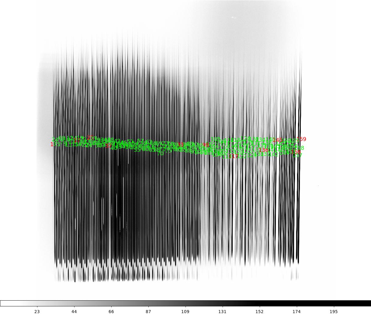
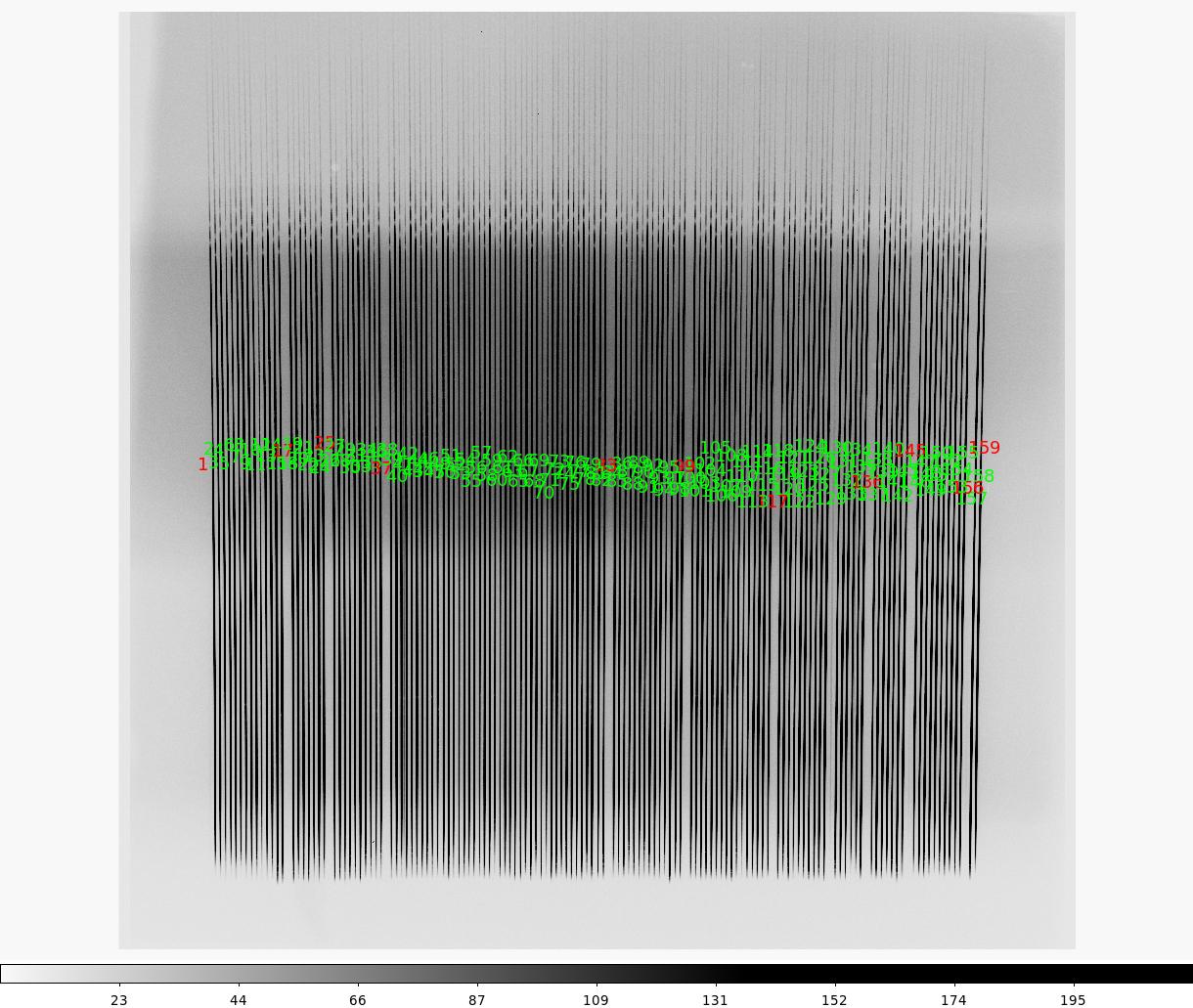
AstrospectU006 Check if the fibres run, from 1 to 150, from right to left or from left to right
on the detector. Create new region files (binning 1x1, 2x2) if the current ones (for the old WHTWFC detector ) do not
fit the position of each fibre spectra on the CCD.
| Notes: Fibres run, from 1 to 150, from left to right on the detector, contrary to the old WHTWFC detector used with WYFFOS. New region files have been created for binning 1x1 and 2x2 and ca be found at /home/whtobs/AF2/ds9Reg/af2bin1_red4.reg /home/whtobs/AF2/ds9Reg/af2bin2_red4.reg. |
AstrospectU007 Calculate the separation between two consecutive fibres in the CCD in the spatial direction (X direction). It
should be ~22.5 unbinned pixels, corresponding to a pixel size of 15 micron.
| Notes: The average separation between two consecutive fibres is 22.45 pixels (11.2 binned pixels). This was measured with the IRAF task "imexam", by measuring the centroid in the spatial direction of the arc lines in consecutive fibre spectra. |
AstrospectU008 Calculate the distance in pixels between two consecutive fibres in a fibre trio in the spectral
direction (Y direction). It should be ~54 unbinned pixels, corresponding to a pixel size of 15 micron.
| Notes: The average distance between two consecutive fibres in a fibre trio in the spectral direction is ~56.2 pixels (27.9 binned pixels). This was measured with the IRAF task "imexam", by measuring the centroid in the spectral direction of the arc lines in consecutive fibre spectra. |
AstrospectU009 Calculate the maximum offset in the spectral direction from the upper fibre of the trio at the left/right side of the CCD (e.g.#159) compared to the
lowest fibre (e.g. #75). Use the lines in an arc frame.
| Notes: In normal reflection mode, the average maximum offset from the upper fibre of the trio in the left/right side of the CCD compared to the lowest fibre in the centre is ~140 pixels (71.5 binned pixels). This means a maximum wavelength shift of less than 5% of the total spectral range, with wavelength shifting to redder wavelengths in the central fibres. These offsets were measured with the IRAF task "imexam", by measuring the centroid in the spectral direction of the arc lines. |
AstrospectU010 Calculate the minimum usable exposure time on the focal
station on which the device is to be used most commonly. This can be done
by carrying out a linearity test at low shutter speeds. Write down the method
and the results. As this is generally set by the shutter in the instrument
itself it will not usually need to be recalculated for every CCD. The commissioning
astronomer and the instrument specialist should satisfy themselves that this
has been done for the station in question.
| Notes: Detector lamp flats were taken with exposure times in the range 0.2 - 8 sec, as in PerfU009. To illuminate uniformly the CCD, a white lamp flat was placed inside WYFFOS. The count level values were measured over a small region of 200x200 pixels in the centre of the images. The exposures were taken in slow readout and binning 1x1.
See linearity error (%) vs exposure time plot. Linearity becomes stable, < 0.1%, for exposure times above 3 sec. Hence, given these results, the recommended exposure time to avoid the effect of the shutter is 3 sec. Exposure times of 2 sec might still be fine, but it is not recommended to expose less than 2 sec. |
AstrospectU011 Measure the relative throughput of the AF2 fibres with Red+4.
| Notes: For measuring the relative fibre throughput, sky flats were taken in circle configuration with a low resolution grating (R316R). The sky spectra was extracted from each fibre, and the mean flux, in the spectral range 3900-9200A, was compared to the mean flux for all the fibres. The throughput of AF2 fibres, relative to the mean of all fibres, can be seen here. |
AstrospectU012 Take exposures of a spectroscopic flux standard under the usual conditions for measuring throughput (low resolution grating). Conditions should be photometric and seeing good and stable. Either reduce the data and note the results here.
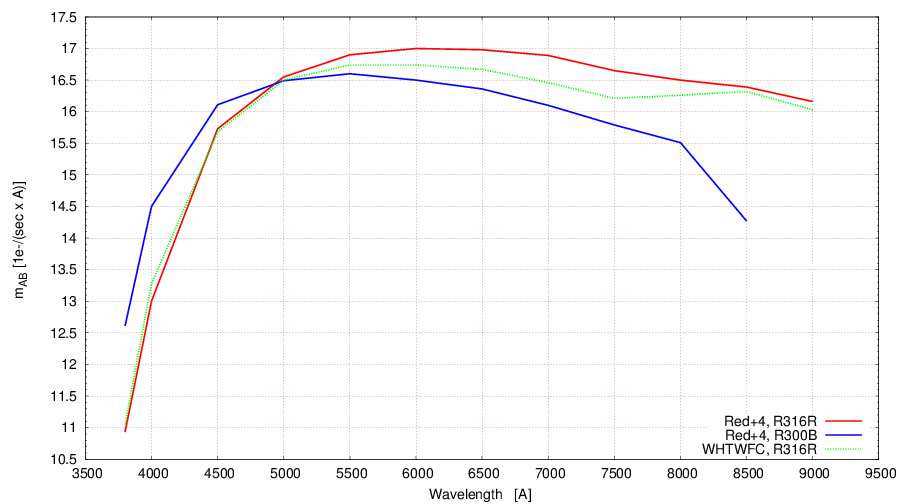
| Notes: The throughput of the overall AF2+WYFFOS system (atmosphere, telescope, prime focus corrector, AF2, WYFFOS) plus the new Red+4 detector was measured for the gratings R300B and R316R in May 2013, through the observation of a B2 IV star placed at 2-3 fibres close the the centre of the AF2 plate, to fibre positioning errors due to distortion effects. The measurements were made in a seeing of ~ 0.9 - 1.0 arcsec (according to the ING DIMM), and no aperture correction was applied; the measurements refer to the numbers of photons entering the 1.6-arcsec apertures of the science fibres, i.e. they will be typical of observations of stellar objects made in this seeing, through a fibre with close to median throughput. The table below show, as a function of wavelength, the measured mAB zeropoints, i.e. the AB magnitude of a star giving 1 electron per second per Angstrom when observed at zenith, for Red+4 and for the old WHTWFC. The measured zeropoints are also shown in the plot.
|
AstrospectU013 Estimate the level of fringing in the Red+4 detector, and compare with the fringing in the old WHTWFC CCD.
| Notes: QTH lamp flat exposures were taken with a level of counts of ~30,000 ADUs, using the grating R316R centred at 6500A. The lamp spectra were extracted and smoothed to average the signatures of fringing. The fringing modulation was obtained by dividing the extracted lamp espectra by the smoothed one. The plot compares the fringing in Red+4 (in red) and WHTWFC (in blue) detectors. While for old WHTWFC the fringing level become very high from 7000 A on, up to ~25% at 9000 A, for Red+4 keeps below 1% for all the spectral range. |
AstrospectU014 Confirm that the slit unit-to-detector reduction factor
expected is reproduced with this CCD; ie. calculate what width of fibres should
project to in terms of the FWHM of the arc lines, and sky lines. Measure this at best
focus position.
| Notes: With any spectrograph configuration, the FWHM of the arc lines is ~1.8 binned pixels (~3.6 unbinned pixels) in both spectral and spatial direction. In the case of sky lines, the FWHM is ~2.4 binned pixels (~4.8 unbinned pixels). The differences between arc and sky lines FWHM is due to different optical path and illumination beam from the sky and from the calibration lamp unit. This confirms that the slit unit-to-detector reduction factor expected is reproduced with this CCD. |
2.3.3 Other device specific tests or comments.
| Notes: Ghosts: The usual ghost seen in the bluer region (bottom half) of the old WHTWFC is also visible in the Red+4. In the case of Red+4, the ghost is seen on the top half of the CCD, which corresponds to the bluer part. |
2.4 Software tests
SoftU001 The software should detect illegal windows and implement
legal ones when requested. Try defining windows outside of the physical
range of the device and note the software response and whether it is expected.
Check that no windows are saved in the controller particularly window 0.
| Notes: It works for illegal windows, the software does not warn the user. In general, the windowing is not performed correctly in the y direction. E.g. for a window [500:1500; 1000:2500], the section in the x axes is done correctly, but in the y direction it selects a section of 1500 pixels, but starting at y=1, instead of y=1500. |
SoftU002 The software should detect illegal attempts to bin and implement
legal ones when requested. Try to bin in the following, way and note the software
response and whether it is as expected: BIN 2x2, BIN 1000x1, BIN, 4x1 BIN
2000x2, BIN 1x4
| Notes: The software complains when an illegal binning is set: "UDASCamera: ErrorInfo exception: Invalid binning factors" |
SoftU003 Check that all the information held in the FITS header is
correct for this CCD. On the WHT the detectors definition file will have to
have this detector added, along with the gains and readout noises for all
readout speeds.
| Notes: FITS header information is ok for this CCD. Red+4 has been added to the WHT detectors definition file. |
3 Acceptance Tests
3.1 Delivery
Notes: All performance documentation relating to this camera can be found at: http://www.ing.iac.es/Engineering/detectors/g3_ultra_red%2B4.html and http://www.ing.iac.es/astronomy/instruments/af2/detector.html All engineering information can be found here:
http://www.ing.iac.es/~eng/detectors/SDSU/hardware/SDSU_wiring.htm |
3.2 Performance
The commissioning astronomer should accept that the chip is configured in an acceptable way
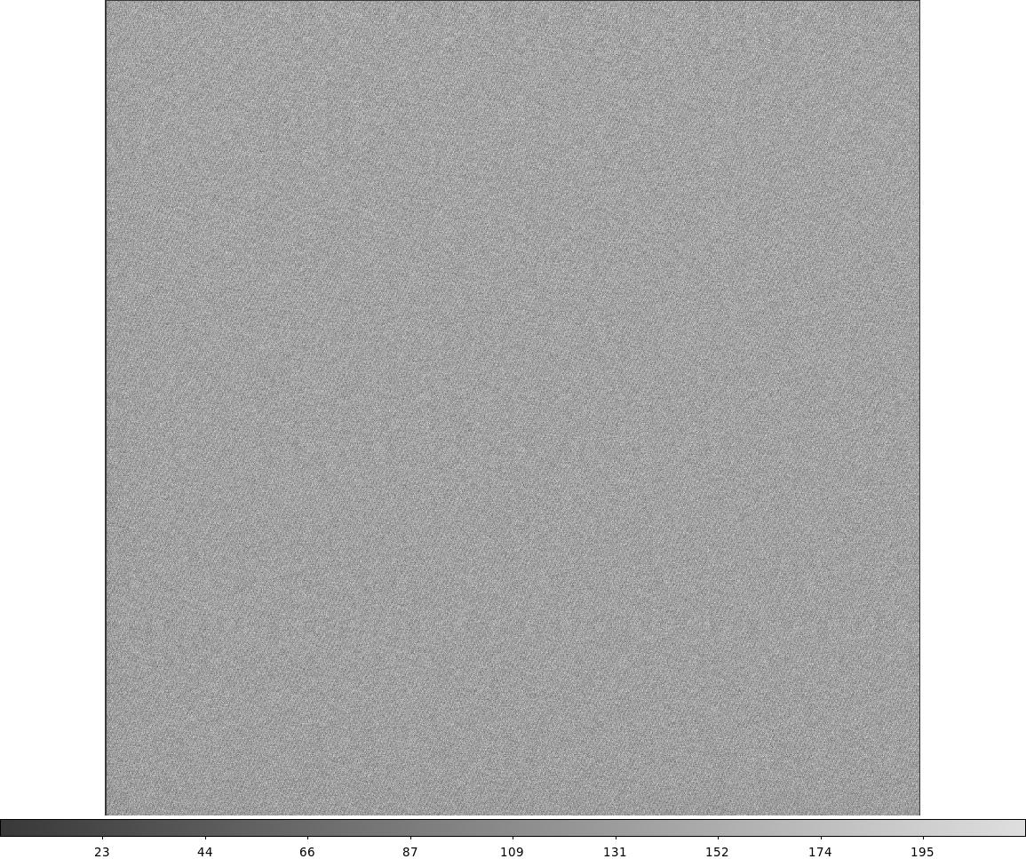
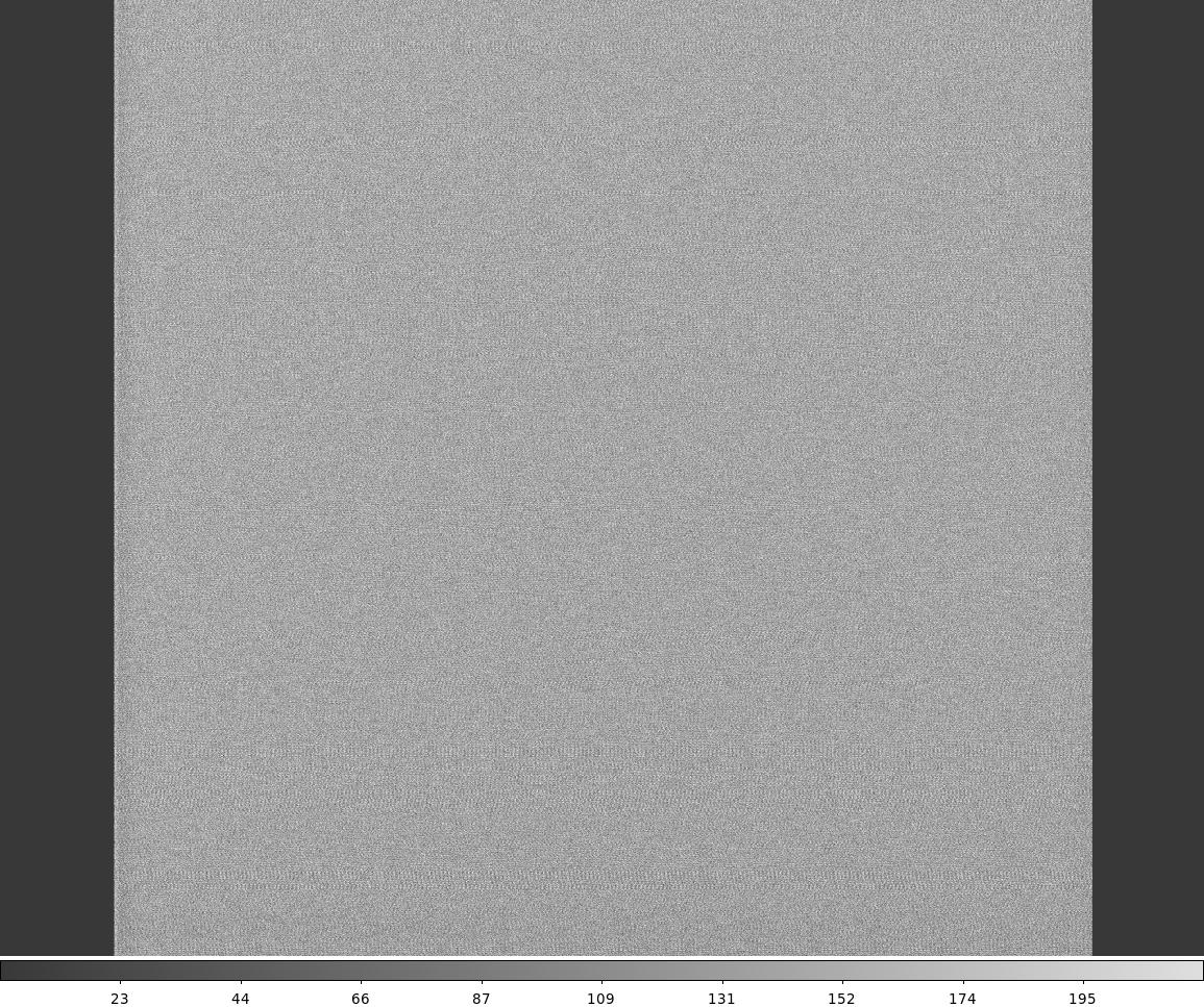
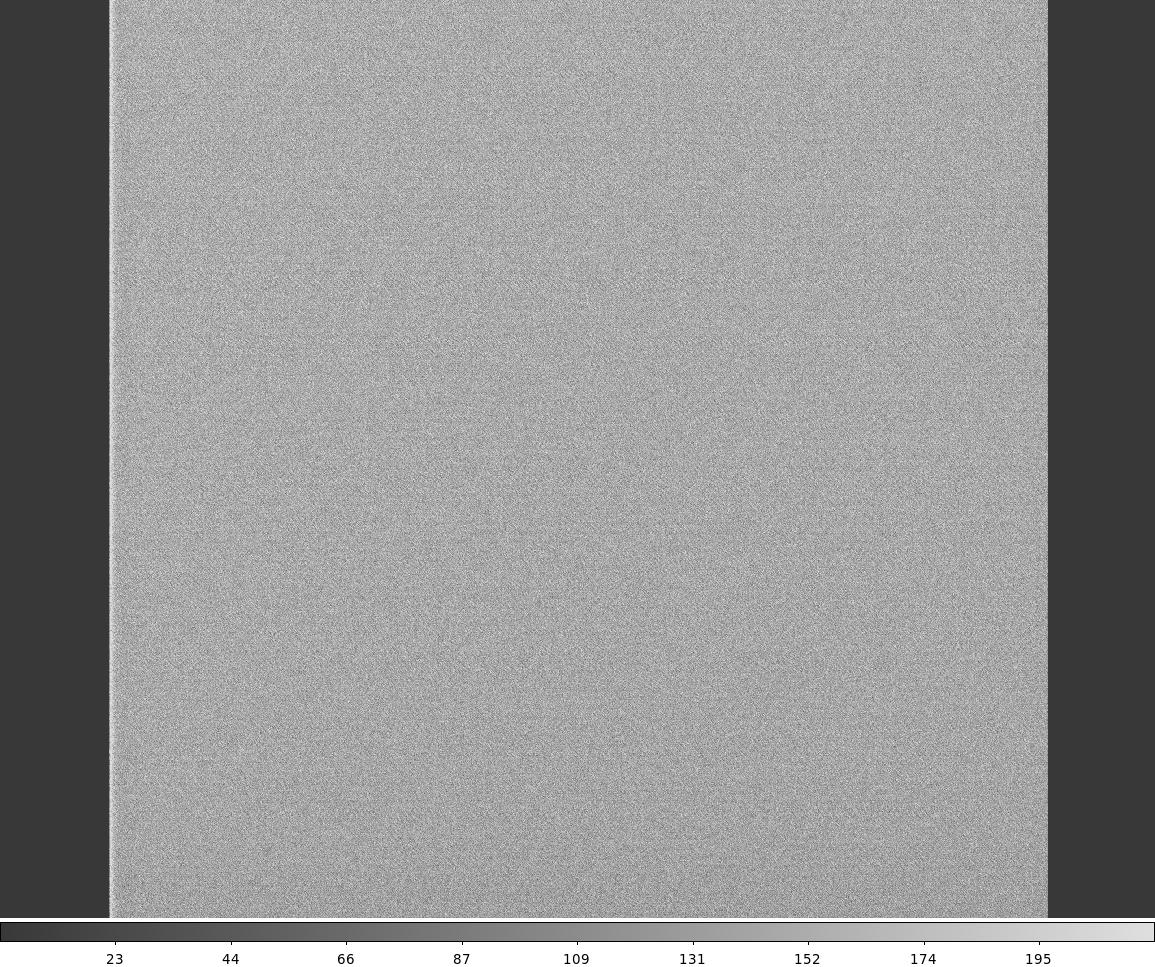
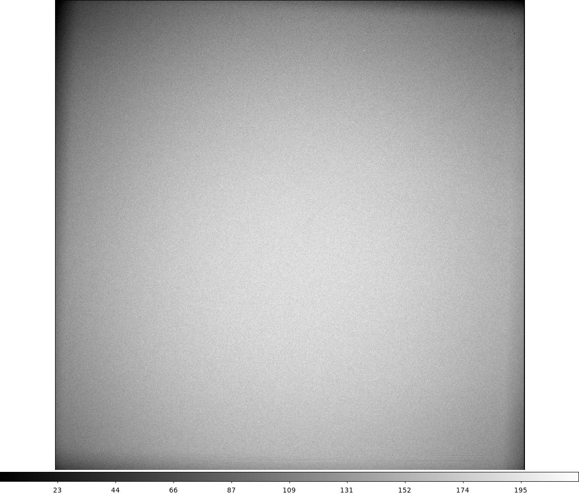
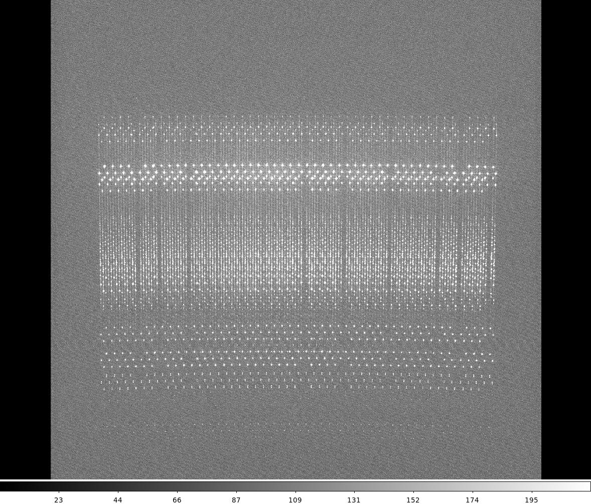
| Notes: All tests concluded that RED+4 on WYFFOS is configured in an acceptable way. The test performed with Red+4 on PFIP concluded that the performance of this detector is not acceptable to be used on PFIP. Main reasons: 1. Dark banding effects along x direction due to saturated targets. See example 2. CCD windowing not performing correctly. See SoftU001. |
3.3 Acceptance
If improvements have been agreed, or deliveries are yet to be received, this section should not be completed. If the CCD is acceptable in its current state, this document should be signed off by the people below.
Commissioning Astronomer (ING): Lilian Dominguez Palmero
Commissioning Engineer (ING): Andy Ridings
Head of Engineering (ING):
When this document has been completed. it must be held by the detector section.