WHT-ISIS-8 WHT ISIS Polarisation
Hardware Design Document
V.E. Austin
Issue 1.1; 08/05/96
Contents:
1.1 Purpose
1.2 Definitions, acronyms and abbreviations
3.1 Physical Description
3.2 Electrical Description
3.2.1 MVME 147-011 Microcomputer
3.2.2 TM1x7 Transition Module
3.2.3 XVME 240 Digital Input/Output - DIO
3.2.4 XVME 220 Digital Output - DOUT
3.2.5 VME 44-4E Stepper Motor Controller
3.3 Parts List
4.1 Physical Description
4.2 Electrical Description
4.2.1 VME Interface
4.2.2 EDM-453 Stepper Motor Drive Card
4.2.3 Power Supplies
4.3 Parts List
5.1 Physical Description
5.2 Electrical Description
5.3 Parts List
6.1 Mains Wiring
6.2 Power Supply / Chassis Wiring
6.3 Top Polarisation Waveplate
6.4 Bottom Polarisation Waveplate
APPENDIX A.
DOCUMENT HISTORY
1. Introduction
1.1 Purpose
This document describes the electronic and computer hardware used in the
ISIS polarisation module control system.
The intended readership of this document is those who wish to understand
the ISIS polarisation module hardware design. Those users involved in the
maintenance of the ISIS polarisation module at the hardware level will
also benefit from reading this document.
1.2 Definitions, acronyms and abbreviations
ISIS Intermediate-dispersion Spectrograph and Imaging System
ISISP ISIS Polarisation
2. Description
The ISIS Polarisation module consists of two mechanisms. These mechanisms
are the half-wave polarisation plate which is generally used for linear
polarisation; and the quarter-wave plate, generally used for circular polarisation.
To use either of these mechanisms the waveplate must be inserted into the
beam where it can either be set to a specified angle or rotated continuously.
When the polarisation module is required for circular polarisation the
positions of the two waveplates must be physically swapped (i.e. the half
waveplate is placed in the top mounting and vice-versa). In order for the
software to maintain the mount positions of the waveplates, the waveplate
mechanisms are referred to as the top and bottom waveplates, which is the
convention followed in all the hardware design and documentation.
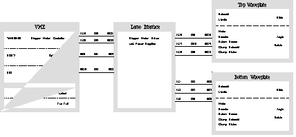
The ISISP control electronics consists of two sub-racks which are mounted
on ISIS. The two sub-racks are the VME crate and the Lemo interface unit.
The VME crate controls and monitors the status of the ISISP mechanisms
via interface boards accommodated in the VME crate. The Lemo interface
unit redistributes signals from the mechanisms to the relevant VME port.
The Lemo interface unit also contains two power supplies and the stepper
motor drive cards for the waveplate motors.
2.1 System Schematic
3. VME
3.1 Physical Description
The ISISP VME is a 4U high 550 mm deep 19 inch sub-rack. It has a 7 slot
horizontal VME backplane and power supply. Three interface cards are fitted
along with a transition module. The transition module provides the connection
to the network and system console via the P2 connector on the backplane.
The interface cards comprise a stepper motor controller, a digital input/output
module and a digital output module. The stepper motor controller card connects
to the rear connector panel via the P2 connector on the backplane whilst
the remaining two interface cards connect to the rear connector panel via
connectors on the front panel of each card. The VME crate also contains
a 40 _C thermal switch mounted on the top panel and a fan fail monitor
and output module located between the backplane and power supply. The fan
filter medium is accessible from behind the front panel. The mains switch
is also behind the front panel, mounted on the left-hand side. This switch
controls the mains to the VME power supply and also switches the mains
to the IEC outlet on the rear of the VME.
3.2 Electrical Description
The processor card used is a Motorola MV147-011 with an TM1x7 transition
module providing four RS232 ports, an Ethernet connection, a printer port
and a SCSI interface. The three I/O cards used are:-
1 off OMS VME44-4E Stepper Motor Controller
1 off XVME 240 Digital Input/Output (DIO)
1 off XVME 220 Digital Output (DOUT)
3.2.1 MVME 147-011 Microcomputer
This card is a 32-bit microcomputer system containing a MC68030 MPU with
a clock speed of 25MHz, a MC68882 floating-point coprocessor and 4MB of
memory. It connects to both P1 and P2 on the VME backplane using the latter
to connect to a transition module. The ethernet address is 08003E22AF09.
3.2.1.1 Setup
ROM Configuration
The ROM is configured in two banks, U22 and U30 form bank 1, U1 and
U15 form bank 2. Only bank 1 is used which is configured by J2. This is
set for 64K x 8 PROM by linking the following pairs of pins on J2
Link Pins 2 & 4
Link Pins 5 & 7
Link Pins 14 & 16
Link Pins 13 & 15
System Controller
The MVME147-011 is selected as the system controller. Link J3
Serial Port 4
Receives RTXC4 J8 Pins 2 & 3 linked
Receives TRXC4 J9 Pins 1 & 2 linked
3.2.2 TM1x7 Transition Module
The transition module provides the interface between the MVME147-011 processor
card and the external peripherals. It provides 4 serial ports, a printer
port, a SCSI interface and an ethernet connection.
3.2.2.1 Setup
Serial Ports 1,2,3 and 4
All ports are configured for DCE operation using headers X1, X2, X3
and X4. The correct link orientation is shown on the PCB silk screen. Headers
X6, X7 and X8 have no links made.
3.2.3 XVME 240 Digital Input/Output - DIO
This card provides 8 ports of TTL level digital input and output, each
port being 8 bits wide. Ports 0 to 3 (connector JK1 on the front panel)
are allocated as inputs whilst ports 4 to 7 (connector JK2 on the front
panel) are allocated as outputs.
3.2.3.1 Setup
Base Address
0xD000 1(A10), 2(A11) and 4(A13) of S2 closed.
3(A12), 5(A14) and 6(A15) of S2 open.
Address Space
Short I/O Access J2B linked, switch 8 of S2 closed.
Supervisor/non-privileged mode
Supervisory only mode
Switch 7 of S1 open.
Address Modifier
Short I/O used, DIO will respond to 2DH only
J2B linked, switches 7 open and 8 closed of S2.
Interrupt Level
No level selected Switches 1, 2 and 3 of S1 closed.
Interrupt Input Edge Detection
Not required as interrupts are not used
J3 to J10 all linked on B.
3.2.3.2 Channel Allocation
Inputs
Port 0


Port 1


Port 2


Port 3


Outputs
Port 4


Port 5


Port 6


Port 7


3.2.4 XVME 220 Digital Output - DOUT
This card provides 32 channels of opto-coupled digital output. Each channel
has a positive and negative connection so all channels are completely isolated
and any load up to 30V and 100mA can be controlled. Channels 0 to 15 are
available via JK1 on the front panel and channels 16 to 31 via JK2.
3.2.4.1 Setup
Base Address
0xC800 1(A10), 3(A12) and 4(A13) of S1 closed.
2(A11), 5(A14) and 6(A15) of S1 open.
Address Space
Short I/O Access J2B linked, switch 8 of S1 closed.
Supervisor/non-privileged mode
Supervisory or non-privileged mode
Switch 7 of S1 closed.
Address Modifier
Short I/O used, DOUT will respond to 29H or 2DH
J2B linked, switch 7 and 8 of S1 closed.
3.2.4.2 Channel Allocation


3.2.5 VME 44-4E Stepper Motor Controller
This card provides 4 independently controllable axes each with encoder
feedback. Each axis has a step and direction output to drive the motor
and has positive and negative limit inputs to provide hardware safety limits.
A datum input is also provided to move the motor to a known position. All
connections are made via the P2 connector on the VME backplane.
3.2.5.1 Setup
Base Address
0xFC00 A4, A5, A6, A7, A8 and A9 linked on J25 and J26.
A10, A11, A12, A13, A14 and A15 not linked on J25.
Address Modifiers
Default setting AM1 and AM4 linked on J26.
AM0 and AM5 not linked on J26.
Interrupt Selection
IRQ5 IRQ5 linked on J15.
IRQ1, IRQ2, IRQ3, IRQ4, IRQ6 and IRQ7 not linked on J15.
J1 linked on J35.
J2, J0 and USER not linked on J35.
Limit Polarity Selection
Channel X, Y, Z and T active Lo
Linked on J24.
Encoder Bias Selection
Default setting T and Z encoder bias, no links on J11
X and Y encoder bias, no links on J14
I/O and Pull-up Select
User definable I/O disabled
All links removed on J32 and J34
I/O output driver I.C.s U31, U33 and U34 removed
3.2.5.2 Channel Allocation

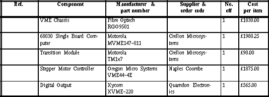
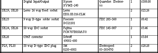
3.3 Parts List

4. Lemo Interface
The Lemo Interface unit provides the wiring interface between the ISISP
module and the VME controller. It also contains the power supplies and
the stepper motor drive cards for the stepper motors used in the module.
4.1 Physical Description
The ISISP Lemo Interface Unit is a 3U high 386 mm deep 19 inch enclosed
sub-rack. The hinged front panel allows internal access, while the front
panel mounted Lemo connectors provide the interface to the ISISP module.
The rear panel provides the interface to the VME controller via two D-type
connectors and two Lemo connectors. Inside the sub-rack are two power supplies
and two stepper motor drive cards. The sub-rack was constructed from a
Schroff ratiopac kit with additional components allowing recessed mounting
of the eurocards.
4.2 Electrical Description
The interface between the ISISP module and the control electronics is via
a number of cables terminated with Lemo connectors at both ends and routed
through ISIS. The signals are grouped depending upon which assembly they
originate from and their function. The function of the Interface Unit is
to re-distributed these signals to the required VME port or stepper motor
drive.
4.2.1 VME Interface
The interface to the VME cards is via 50 way IDC connectors. This type
of connector is unsuitable for a wiring loom such as the one in the Lemo
Interface so the cables between the VME and the Lemo Interface are terminated
with a standard 50 way IDC connector and a 50 way IDC D-type connector
at each end respectively. The table below gives a cross-reference of pin
numbers between the two types of connector.


4.2.2 EDM-453 Stepper Motor Drive Card
This is a commercially available bipolar chopper driver (3A per phase,
45V) designed specifically to drive the Portescap two phase stepper motors.
4.2.2.1 Card Setup
Switch 1 (Mode) - OFF Regenerative mode
Switch 2 (D0) - OFF Resolution 64 microsteps per full step
Switch 3 (D1) - OFF
Switch 4 (D2) - OFF
Switch 5 (INT/EXT) - ON Mode and resolution selected internally
Switch 6 (I0) - OFF Phase current 3A
Switch 7 (I1) - OFF
Switch 8 (I2) - OFF
Switch 9 (I3) - OFF
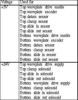
4.2.3 Power Supplies
The Lemo Interface Unit contains two single output power supplies,
providing 5V 12A and 24V 10A respectively. The table below details where
each of the supplies is used.
4.3 Parts List


5. Polarisation Module
5.1 Physical Description
The polarisation module consists of two identical mechanisms, the top and
bottom waveplates, mounted on a baseplate. Connector brackets providing
the interface to the Lemo Interface Unit are also mounted on the baseplate.
Each waveplate consists of a stepper motor, encoder, datum switch, clamp
mechanism and clamp sensor mounted on a slide. The slide can be pneumatically
deployed into the beam with two sensors giving positional information.
The encoder, motor and waveplate holder are all mounted on separate gears
with the following gear ratios:-
motor:encoder = 35:16
encoder:waveplate = 2.4:1
These gear ratios result in one encoder pulse measuring 0.025_ at the
waveplate and one motor microstep measuring 0.01143_, giving approximately
two microsteps per encoder pulse.
5.2 Electrical Description
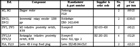
The stepper motors used to rotate the waveplates are Portescap two phase
stepper motors constructed using disc magnet technology and having a holding
torque of 140 mNm or 20 oz-in. The stepper motors have a step angle of
3.6_ and are operated in microstep mode with 64 microsteps per full step.
The encoders are Heidenhain optical, incremental modular encoders with
a resolution of 1500 pulses per revolution. The encoder resolution is increased
by four times (i.e. 6000 p.p.r.) using quadrature decoding at the VME44-4E
card. In order to calibrate the zero-point of the encoders, inductive proximity
switches are used to define the datum position. Inductive proximity switches
are also used to give status information for the solenoid-activated pneumatic
valves driving the clamp and slide sub-mechanisms.
5.3 Parts List

6. Wiring Schedules
The wiring schedules for each of the polarisation waveplates, from the
mechanism assembly through to the VME crate, are available. The colour
convention followed in the wiring schedules is described below.
6.1 Mains Wiring
Brown - Live (240 VAC)
Blue - Neutral
Green/Yellow - Earth Chassis
6.2 Power Supply / Chassis Wiring
Red - +5V
Black - 0V
Yellow - +24V
Green/Yellow - Chassis Earth
Pink - General Chassis Wiring
6.3 Top Polarisation Waveplate (not with this document)
6.4 Bottom Polarisation Waveplate (not with this document)
7. Cable Schedules
All external cables are wired straight through using the following colour
convention:-
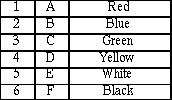
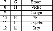
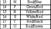
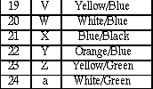
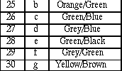
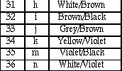
External cables between VME crate and Lemo interface

External cables between Lemo interface and polarisation module

Document History
Issue 1.1 08/05/96 Vicky Austin (RGO) First issue.


![]()


![]()