| UK Astronomy Technology Centre |
Chris Tierney |
| Royal Observatory, Edinburgh |
31st March 2001 |
Overall structure of the NAOMI EPICS software
The NAOMI software is separated, at the top level, into two components:
software for the Wavefront Sensor (WFS) and software for the Nasmyth Calibration
Unit (NCU). In addition, software is required for positioning of the Deformable
Mirror (DM) on the NAOMI Opto-Mechanical Chassis (OMC). This software, for control
over the OMC mechanisms, has been grouped with the software for control over
the WFS.
Positioning of the NAOMI mechanisms is achieved with stepper motors,
which are controlled using OMS VME-8 and VME-44 stepper motor
controller cards. The one exception is the NCU mask mechanism (see below),
which uses a DC motor, controlled from a XYCOM XVME-240 digital I/O card,
to achieve in/out positioning. Other VME cards present in the system are
as follows.
- The XYCOM XVME-240, mentioned above, is for control of TTL levels
(switching of lamps, DC motors, shutter etc) and the sensing of input levels
(NCU mask in/out, reading of A/D converter for the NCU photodiode).
-
The VMIC VMIVME-4145 Waveform Generator card is for generation
of the time-dependent voltages required to drive the NCU tip-tilt calibration
mirror.
-
The VMIC VMIVME-3230 Thermocouple Board is used to measure the
temperature at thermocouples distributed at various locations on the instrument.
A device driver for the XYCOM card is included in the Gemini release
of EPICS used for NAOMI, and one for the OMS cards was developed at HIA
for the GMOS mechanism control records (although this was modified slightly
for the NAOMI project). Software for control of the VME-4145 and VME-3230 cards
has not yet been integrated into the NAOMI mechanism control software.
We deal now with each component in more detail.
Wavefront Sensor components
-
Pick-off X and Y positioning - two stepper motors position the NAOMI
Wavefront Sensor Pick-off mirror. The mirror is used to select a guide
star from the NAOMI field-of-view, who's light will be passed into the
wavefront sensor toward the NAOMI cameras.
-
Fore-optics and Camera Stage positioning - The NAOMI CCD cameras
are mounted on a linear slide which moves along the same axis as the pick-off
X motion. An additional stage, between the two, holds the NAOMI "fore-optics"
comprising a filter wheel, two AtmDC prisms and a lenslet wheel. Both these
stages must be moved in response to any motion of the pick-off mirror,
in order to maintain focus at the CCD cameras.
-
Lenslet selection - The selection of which lenslet to use for NAOMI
wavefront sensing is made using a single rotary stage, mounted on the
fore-optics stage mentioned above. The lenslets must maintain accurate
registration with the CCD camera pixel axes (and binning windows). The
lenslets are not all of equal focal length, requiring that the camera
stage position be dependent upon the current lenslet selection.
-
Filter selection - Selection of the WFS filter is achieved using
a single rotary stage.
-
Atmospheric Dispersion Correction (AtmDC) - The NAOMI AtmDC comprises
two prisms, which are rotated using rotary stages.
-
Opto-mechanical chassis - The OMC holds several components of NAOMI,
and is really a separate major component in its own right. However, the
small amount of EPICS software required for the OMC has been subsumed into
the software for the WFS. The only requirements for automated motion here
are X and Y positioning of the Deformable Mirror (DM). This is performed
in order to maintain alignment of the DM segments with the lenslet array
spots that are seen at the NAOMI cameras.
Nasmyth Calibration Unit
-
Beamsplitter - The beamsplitter is driven by a stepper motor between
in
and out positions. With the beamplitter in-beam, light from the
NCU calibration source will be seen by the wavefront sensor (ie. the NCU
is deployed).
-
Motorised mask - This mask is driven into or out of the NCU beam
by a DC motor. Limit switches at either end of the travel are used to determine
whether the mask has been deployed (or removed) successfully.
-
Calibration source - The NCU calibration lamp is switched on
or off by a TTL voltage generated by the XYCOM-240 card. Light from
the source passes through a shutter, which acts as a variable attenuator
when rotated by its stepper motor, into an integrating sphere. A measure
of the light intensity within the integrating sphere is obtained from a
photodiode mounted in the sphere. The photodiode voltage is amplified,
measured by an A/D converter and recorded in software via the XYCOM-240
card. Light from the integrating sphere then passes through the plane of
the NCU mask and on to the beamsplitter.
General structure of the EPICS database for each component of NAOMI
The various NAOMI mechanisms fall broadly into two classes: those that utilise
steppermotors and those that do not. The software components written for these
mechanisms falls into two classes along the same lines.
-
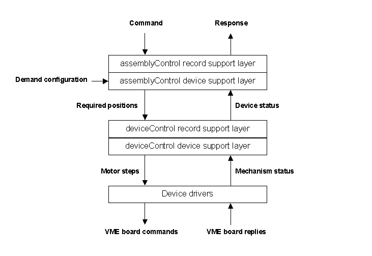
For mechanisms which contain one or more steppermotors, use is made of the GMOS
assemblyControl and deviceControl records. Each stepper motor
(device) is controlled and monitored using a single deviceControl record
(see the description of GMOS records).
These records use the OMS device driver to generate motion in the motors,
accepting as input a demand position in engineering units meaningful to
the user. The records allow the user to datum (index) the mechanisms
using home or limit switches, and to move or jog (step at a constant rate)
the mechanisms. They also allow the developer to configure the use of
encoders, to set the velocities at which each device must move or index
and to specify the whether the system should monitor the power or brake
status of each device.

Over this, related devices are grouped together into assemblies,
each one of which uses one assemblyControl record to sequence the actions
of its component devices. The assemblyControl records add any required
offsets to the user-demanded positions for each device, and perform any
additional calculations required to maintain devices in their correct relative
positions. For instance, the correct position of the Fore-optics stage
is dependent upon the x/y position of the pick-off, whilst the correct
position of the CCD stage is dependent upon both the position of the Fore-optics
stage and the focal length of the selected lenslet array. This calculation
is performed within the "pick-off" assemblyControl record.
-
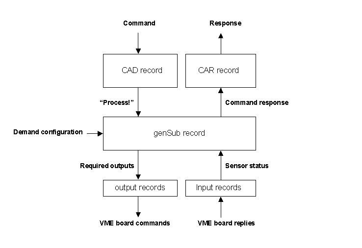
Devices which don't utilise any stepper motors do not need to use the
deviceControl or assemblyControl records. Control over these devices, such
as the DC motor for the NCU mask, is implemented using the Gemini general-purpose
subroutine (genSub) record and standard EPICS records like the binary input
record.

Above each such assembly is a single gemini CAD/CAR record pair. These records form
part of the Gemini standard EPICS interface. However, compliance with the
Gemini interface is not a requirement of the NAOMI software and these records
have been included for convenience only, able to provide a well-defined
command/response interface to higher-level NAOMI software such as the TIDE
DRAMA/EPICS translator or the Python/Channel Access interface. Once an action has been
configured by setting the required fields in the NAOMI database, it can
be initiated by MARKing and STARTing the relevant CAD record. The associated
CAR record will then display an IDLE to BUSY transition as the action starts,
followed by a BUSY to IDLE (or BUSY to ERROR) transition as it terminates.
In fact, a CAD/CAR-like interface is designed into the GMOS assemblyControl record, so
there is no requirement to use the supplied CAD/CAR pair. For components that use only
the genSub record, the CAD/CAR pair should be used by any higher level software.

