| UK Astronomy Technology Centre | Chris Tierney |
| Royal Observatory, Edinburgh | 31st March 2001 |

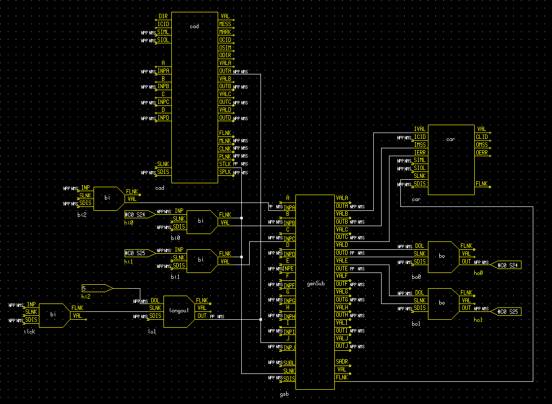
The calibration unit motorised mask is required only to move between in-beam and out-of-beam positions. This is achieved physically with a DC motor. The drive electronics is controlled via two TTL voltages from a XYCOM-240 card, one to drive the motor forward and another to drive backward. The 240 card also accepts input from limit switches, located at either end of the full range of travel of the stage.
The software, therefore, need only assert one output line or the other using standard binary output records, and release that line when the corresponding binary input indicates that the mask is in position (either in or out of the optical path).
Records "bo0" and "bo1" are of DTYP "XYCOM-240" and are scan passive. They are used to modify the two required control voltages. Records "bi0" and "bi1", of DTYP "XYCOM-240" and scan i/o intr (process whenever an input changes), are used to sense the limit switch status.
Record "bi2" (DTYP "Soft channel" and scan passive) holds the current requested direction of motion in its VAL field. Engineering screens modify this field (via channel access) to specify "into beam" or "out of beam" directions for the next motion.
The scan passive gensub record, "gsb", services these records. This record runs the function specified in its SNAM field, and is connected to process whenever one of the limit switches changes, the interlock is asserted or the attached CAD record is instructed to START. The code implements a state machine, with the current record state stored in the J input field of the record. State 5, processed whenever the "ilck" binary input record changes, stops the motor regardless of the current state of the mechanism.
A typical operation involving this database would consist of the following: