Royal Greenwich Observatory,
Madingley Road,
Cambridge CB3 0HJ
Telephone (01223) 374000
Fax (01223) 374700
Internet anj@ast.cam.ac.uk
WHT-ISIS-6
Issue 1.2; 28 May 1996

Royal Greenwich Observatory,
Madingley Road,
Cambridge CB3 0HJ
Telephone (01223) 374000
Fax (01223) 374700
Internet anj@ast.cam.ac.uk
This document describes the architectural design of the VAX software used for controlling the new EPICS-controlled ISIS Polarisation Module. It does not include a description of the software interface to the EPICS system, which is contained in the relevant design documentation for the EPICS system, however it does describe the other interfaces used by the software.
Information contained in this document is intended for use in development of the control software for the replacement ISIS Polarisation Module. However it is eventually intended to replace the 4MS microprocessor system which controls the remainder of the ISIS spectrograph with an EPICS-based controller, so the design of this software has taken into account the need for expansion at a future date.
1.2 Definitions, acronyms and abbreviations
General abbreviations:
4MS 4.2 Meter Microprocessor System, the Forth-based control system standard
EPICS Experimental Physics and Industrial Control System
IOC Input/Output Controller, meaning the VME crate containing the vxWorks CPU which runs the EPICS software and any interface cards
ISIS The triple-spectrograph which is used at the Cassegrain focus of the WHT
ISISP The ISIS Polarisation Module
ISIS PCS The ISIS Polarisation Control System
URD User Requirements Document
vxWorks Wind River Systems' real-time operating system
WHT William Herschel Telescope
1.3 Related Documents
WHT-ISIS-4 WHT ISIS Polarisation Module URD, V.E. Austin 1995.
Functional Specification for the ISIS Polarisation Module, P.D. Jolley & V.E. Austin, Issue 1.2, August 1995.
WHT-ISIS-8 WHT ISIS Polarisation Module System Test Document, F.J. Gribbin & A.N. Johnson, May 1996
The ISIS Polarisation Control System (ISIS PCS) is divided between three processors:
1. Real-time control of the instrument is maintained by the ISISP IOC, which is electronically connected directly to the mechanisms which make up the Polarisation Unit.
2. The Engineering Interface is implemented as a series of EPICS dm2 screens running on a Unix system which can be displayed on any X-windows terminal. The engineering screens permit complete control over the instrument.
3. The User Interface for astronomical use is provided by software running on the WHT system computer, a VAX housed in the WHT control room. This software is integrated with the other WHT instrument control systems and interfaces to the WHT MIMIC display.
All three processors are connected to the Ethernet which forms part of the WHT infrastructure, and communicate using TCP/IP networking.
2.2 Control Interfaces
All control connections between the above processors are implemented using the EPICS Channel Access network protocol over TCP/IP network connections. This gives Unix and VAX client software the ability to read, modify and monitor values associated with named database records in any connected IOC. For use at the WHT, a standard mechanism interface has been developed which uses Channel Access to communicate mechanism command and status information between the VAX software and the IOC. The first implementation of this interface was produced for the WYFFOS spectrograph, and this will be revised for use within the ISIS Polarisation Control System.
The observer's interface is implemented using ICL and an ADAM I-task. An observer issuing an ISIS Polarisation command via ICL causes an ADAM message to be sent to the ISISP I-task requesting that an ADAM action be carried out. The I-task responds by sending commands to the IOC as necessary to implement the requested action. When all IOC commands have completed or when a failure is detected, the action finishes and if necessary a status report is made to the observer's terminal. The status of the ISISP mechanisms is continuously available to the observer on a page of the observer's MIMIC display.
2.3 ISISP Physical Processor Model
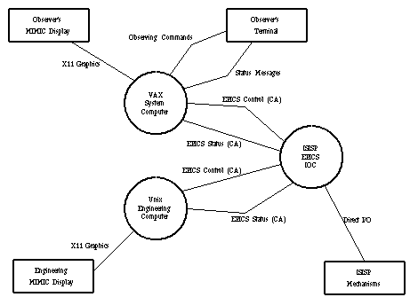
The diagram 
below provides an overview of the physical processors in the ISIS PCS and their
related data flows.
Messages requesting ADAM actions are sent to the ISISP control-task by ICL in response to commands typed by the observer. When the ISISP I-task is loaded a series of command procedures are defined which translate the command-set used by the observer into the ADAM messages known to the I-task. The user-level commands and corresponding ADAM actions are as follows:


3.1.1 HW_POLAR MOVE, QW_POLAR MOVE
This function causes the wave-plate slide to move into or out of the light path. It takes as a parameter the position string "IN" or "OUT". If automatic focussing is enabled, the movement of a slide will cause a focus change command to be sent to the telescope and/or slit-view TV camera. The amount of the focus change for each waveplate is read from the configuration database file (see section 5.5.1 below). Note that the focus adjustment is performed by the ICL procedure, not by the I-task, so this will not occur if the procedure interfaces are by-passed.
3.1.2 HW_POLAR ANGLE, QW_POLAR ANGLE
This function rotates the wave-plate to a particular angle, accurate to 0.2 degrees at any angle, or 0.1 degrees at angles which are an integer multiple of 22.5 degrees. The parameter is the desired wave-plate angle, specified in multiples of a tenth of a degree, in the range 0 to 359.9 Degrees. This command cannot be used while the plate is rotating. At angles which are a multiple of 22.5 degrees the polarisation unit will automatically engage a detent clamp to achieve the higher accuracy and repeatability to the plate angle. The user will be informed whenever the clamp is engaged, and this information is also shown on the MIMIC page - the clamp appears as a small triangle next to the waveplate whenever it is engaged.
3.1.3 HW_POLAR ROTATE, QW_POLAR ROTATE
This function causes the wave-plate to be rotated continuously. The rotation rate is given by the input parameter, which is specified in multiples of a tenth of a Hz, in the range 0.1 to 1.0 Hertz. Continuous rotation overrides the setting of the plate angle. A rotation rate of zero causes rotation to stop and is equivalent to the STOP function. When the plate is rotating it is possible to specify a different rotation rate, but this command has to stop the rotation (including zero-setting the angle encoder) and restart it again at the new speed, thus it can take up to two minutes to perform.
3.1.4 HW_POLAR STOP, QW_POLAR STOP
This function causes the continuous rotation of the wave-plate to be halted, and is functionally equivalent to a ROTATE with parameter zero. Continuous rotation must be halted before a static plate angle can be selected. When the plate stops, the mechanism automatically reinitialises the angle encoder and sets the angle to zero with the detent clamp engaged; this can take up to a minute to perform.
3.1.5 HW_POLAR INIT, QW_POLAR INIT
This function causes the wave-plate angular encoder to be reinitialised by rotating the plate until the zero-point proximity switch engages. The wave-plate will be left at angle zero degrees with the detent clamp engaged.
3.1.6 CHANGE
The standard CHANGE command has been modified to include an option which sets the current polarisation waveplate configuration. This tells the control software about the current mount positions of the two wave-plate optics, as these may be configured for either circular or linear polarisation measurements.
3.1.7 ISISP_FOCUS
The parameter to ISISP_FOCUS controls whether the telescope or slit-view TV receive focus adjustment commands when the waveplate slides are moved in or out of the beam. The parameter can be NONE (which disables automatic focussing - this is the default), TEL (for telescope only), TV (slit-view TV only) or ALL. If no parameter is given, it initiates a dialogue with the user to select the setting to be used. When focus adjustment is turned on, the focus is assumed to be correct for the current positions of the waveplate slides, thus just running ISISP_FOCUS will not cause the focus position to change.
3.1.8 ISISP_CPOL
This is the astronomical circular polarisation observing procedure, modified for use with ISISP.
3.1.9 ISISP_LPOL
This is the astronomical linear polarisation observing procedure, modified for use with ISISP.
3.1.10 ISISP_INIT
The parameter to this procedure is either the word ALL, or an ISISP mechanism name as given in section 3.2 below, and causes the relevant mechanism(s) to be initialised. For slide mechanisms the initialisation position is OUT. For angle and spin mechanisms initialisation causes the waveplate to be moved to the encoder datum position and the clamp engaged. Note that initialising the slide mechanisms with this procedure will not cause any change to the telescope or slit-view TV focus positions, thus these may need subsequent manual adjustment.
3.1.11 ISISP_BEGIN
This procedure starts the 10 Hz Channel Access POLL action running, connects the I-task to the EPICS IOC, updates the noticeboard items and MIMIC display, and reads the configuration file.
3.1.12 ISISP_END
This procedure stops any continuous rotation of the waveplates, moves the slides to their OUT positions, then causes the ISISP I-task to exit.
3.2 ISISP Mechanism Subactions
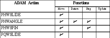
The following table lists the ADAM mechanism control actions provided by the ISISP I-task along with the subactions implemented for each action. This list only includes those actions directly controlling or sensing an ISISP mechanism. Further actions are listed in Section 3.5 below.


3.3 Mechanism Subactions
As listed above, subactions from a standard set are defined for each ADAM action. These standard subactions are defined as follows:
MOVE This function corresponds to a command which requests a change in some controllable aspect of the mechanism, supplying the new value for the mechanism state or position.
DATUM This function corresponds to a command to drive the mechanism to a datum switch which is used as a calibration marker for the encoder.
STOP This function corresponds to a command to stop a currently active mechanism motion. This can only be used with a mechanism which takes an appreciable amount of time to complete a movement.
UPDATE This function is used when a status update is required and this update requires an ADAM action to initiate some processing in the IOC. This function is only applicable to those mechanisms which do not maintain a continuous status update. ISISP does not have any mechanisms of this type.
STATUS The status function implemented in previous WHT instruments is redundant for EPICS-based control systems which use Channel Access monitors to maintain a continuous status value.
3.4 ADAM Action Parameter Types and Ranges
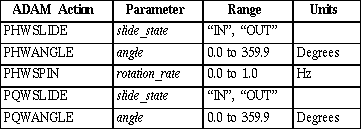
The mechanism actions given above take the following parameter to their MOVE subaction:


The mechanism subactions other than MOVE do not take any parameters.
3.5 Additional ADAM Actions
The following ISISP I-task actions are not directly associated with a specific mechanism:


Information from the ISISP EPICS database is written by the control task to an ADAM noticeboard named ISISP. The mimic process and the header-collection task read this noticeboard, and if required other tasks may also do so. Most mechanisms (denoted here as mech) have the following noticeboard items defined:

All mechanisms have the noticeboard item current defined. This item is a character array where a
mechanism holds its numerical position as a text string for display on the MIMIC, or as one of a
small number of fixed strings indicating discrete states or positions. All mechanisms which are
intended to have status displayed on the MIMIC have the mim_status noticeboard item defined to
indicate the display colour.
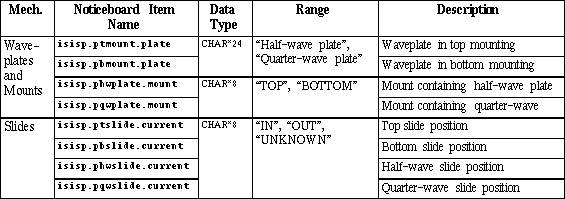
The table below shows details of the possible values for various noticeboard items. Because of the requirement to be able to switch the locations of the two wave-plates, wherever a mechanism name starts phw or pqw the value contained in this noticeboard item will be identical to that in one or other of the real mechanisms with names beginning pt or pb.


5.2 User Unit Conversion
The values input by the user to specify a mechanism position will not necessarily be identical to the values required by the EPICS database. Similarly, the status values returned by the database may not be precisely what is required to be displayed to the user. The values input by or displayed to the user are in `user units' and are converted either by:
EPICS Where the mechanism demand position or status return are implemented as a multi-bit binary record type, the user values are converted between one of a discrete series of strings and the associated database value by the EPICS Channel-Access server. An EPICS Channel Access server error is reported if an input string cannot be matched.
I-Task Specific conversions are done by the VAX I-task software for particular mechanism types. These conversions are described below.
5.2.1 Input Conversions
The following table shows the values and units input by the user and the corresponding units to be passed to the EPICS database.

5.2.1.1 Wave-plate Mounting
The functional specification describes how the polarisation unit is required to be used for circular polarisation measurements, during which the positions of the two wave-plates are physically swapped (i.e. the half-wave plate is placed in the top mounting and vice-versa). In order to maintain the correct command mappings and MIMIC display at all times, the I-task maintains a record of the mount position of the two wave-plates in the noticeboard items isisp.phwplate.mount and isisp.pqwplate.mount. This configuration data can be changed using the CHANGE_WP action, and is recorded in the ASCII file ISISP.DAT which is manipulated using the actions SAVE_CONFIG and READ_CONFIG. The position information is used to map all wave-plate actions to their correct mechanisms, applied according to the following table:


5.2.1.2 Wave-plate Angle
The interface to the EPICS database requires the angular position of the wave-plate to be specified as an integer, with one unit representing an angle of 0.1 degrees. The user specifies the angle as a real number of degrees, which the I-task multiplies by 10 and rounds to the nearest integer before passing the value to the database. Note that the noticeboard values are maintained as real numbers.
5.2.1.3 Wave-plate Rotation Rate
The interface to the EPICS database requires the rotation rate of the wave-plate to be specified as an integer, with one unit representing a rate of 0.1 Hertz. The user specifies the rate as a real number of Hertz, which the I-task multiplies by 10 and rounds to the nearest integer before passing the value to the database. Note that the noticeboard values are maintained as real numbers.
5.2.2 Output Conversions
Several ISISP noticeboard items are not simple copies of the corresponding values in the EPICS database. The following table shows the Noticeboard items derived from each mechanism status value. These values will be updated whenever a Channel Access monitor is triggered on the relevant EPICS database values.


5.2.2.1 Telescope Focus Offset
When the polarisation waveplates are inserted into and removed from the light beam, the focus position of the telescope must be changed to accommodate the different optical path length introduced by the waveplate's presence. The focus offset for each waveplate is obtained from the the ASCII file ISISP.DAT (see section 5.5.1 below). This noticeboard item is used to communicate the sign and magnitude of the telescope focus offset required between the I-task and the ICL procedure which initiated the action.
5.2.2.2 Slit-View TV Focus Offset
The light beam to the slit-view TV camera is reflected back through the waveplates, thus in addition to adjusting the Telescope focus it is necessary to adjust the TV camera focus when the waveplates are inserted or removed. The focus offset for each waveplate is obtained from the ASCII file ISISP.DAT as with the telescope focus above.
5.2.2.3 Wave-plate Angle
As with the input conversion, the current wave-plate angle is represented in the EPICS database as an integer which must be converted into degrees as a real number before presentation to the user. This conversion (division by 10) is performed in the I-task before the value is placed in the relevant noticeboard items.
5.2.2.4 Wave-plate Rotation Rate
Similarly, the wave-plate rotation rate is represented in the EPICS database as an integer and must be converted into Hertz as a real number. The conversion (division by 10) is performed by the I-task before the value is placed in the relevant notice-board items.
5.2.2.5 Wave-plate Mounting
As described in section 5.2.1.1 above, the I-Task maintains a record of the mount location of the waveplates. This information is also used in reverse to update noticeboard items containing the current status of the half-wave and quarter-wave plate mechanisms. This allows the DAS headers for ISISP to remain compatible with the old ISIS D-task items. The mapping between the mount locations and the mechanism data to be used is similar to that given in the table in section 5.2.1.1 above.
5.3 Observer's MIMIC Display
The observer's MIMIC for ISISP consists of modified versions of the standard ISIS slit-area display and overall system status. An update of the ISIS summary page has also been produced. The changes to the existing pages are as follows:
z Remove the anamorphotic lens display, which will never now be installed. The screen positions of the other mechanisms will be adjusted to take up the space which this allows.
z Make the text for the names of the two wave-plates into noticeboard items, to reflect the current setting via the ADAM CHANGE_WP Action.
z Add graphic and/or text items for the status information which is new for the ISISP system:
D Waveplate angle detent/clamps,
D Mechanism connections,
D VME Thermal monitoring
D IOC communication status.
z Rename the noticeboard items used to show the status of the existing mechanisms to those provided by the new software.
z Rename and move the polarisation segments and update commands as necessary.
z Create dummy update_anamorph, update_hwpolar and update_qwpolar commands to avoid breaking the existing ISIS D-Task.
5.3.1 Mechanism Status on the MIMIC
The colour of a displayed mechanism depends on the status value in the mim_status noticeboard item for that mechanism. The status values used and their corresponding colours shown on the display are as follows:

5.4 DAS Interface Definitions
5.4.1 Headers for Observation files
The ISISP headers are defined in a modified version of the Packet Definition File INSTISIS which is part of the PDF software subsystem. The changes to this file are the minimum required to maintain system operation of the existing ISIS D-Task while at the same time using the ISISP noticeboard values. The modified header items are as follows:


The two headers ISIHWMNT and ISIQWMNT are new header items, and indicate which mounting
the wave-plate is installed in.
5.4.2 DAS Automatic Logging
The ISISP system does not provide any information for the DAS automatic log.
5.5 Run-time File Usage
5.5.1 Configuration File
The ISISP I-task uses the file WHTUSER_ISISP_DIR:ISISP.DAT to maintain a record of the thicknesses and mount position of the two waveplates. This file is in a human-readable ASCII format, although the configuration will normally be maintained and updated using the CHANGE observing command which uses the ADAM actions CHANGE_WP and SAVE_CONFIG. The file is read by the I-task on receipt of the action READ_CONFIG. The CHANGE observing command automatically purges all but the last 5 versions of the configuration file. If the waveplate thicknesses change in the future, it will be necessary to modify these configuration items by hand as there is not mechanism within the I-task to change the thickness data.
The file is divided into several sections, with each section header being a name enclosed in square brackets [section header]. Within each section are a number of lines each comprising a configuration item name and its associated value, separated by an equals sign item name = value string. The file may also contain blank lines, and comments which are introduced using a semi-colon ;. In all cases the capitalisation of names is important; names may include spaces and punctuation, and value strings may incorporate any printable ASCII character.
The ISISP I-task uses the sections waveplate configuration, PHWPLATE and PQWPLATE. Additional sections and data items may be added to the file and will be retained when the configuration data is saved, but such items will not be used or updated by the ISISP I-task.
5.5.1.1 waveplate configuration
This section contains one item named top waveplate which has the value QWP or HWP, indicating the waveplate installed in the top mounting.
5.5.1.2 PHWPLATE
This section contains data giving the focus offsets for the half-wave plate. The data items are named tel focus offset and tv focus offset and their values give the focus offset to be applied when the waveplate is inserted into to the light path, in user units (mm and steps respectively).
5.5.1.3 PQWPLATE
This section contains data giving the focus offsets for the quarter-wave plate. The data items are as for the half-wave plate above, but note that the quarter-wave plate vignettes the slit-view TV camera so its focus offset is given as zero.
5.5.1.4 Default configuration file
When the ISISP subsystem is built, a default configuration file WHT_ISISP_DIR:ISISP.DAT is fetched from CMS which is as follows:
; Configuration data file for the ISIS Polarisation Unit
;
; Created  Andrew Johnson {RGO}  3-May-96
;
; NB capitalisation of all items is important - do not fiddle!

[waveplate configuration]
; The data item "top waveplate" should be either QWP or HWP
top waveplate = QWP

[PHWPLATE]
; The units of the focus offset data are as used at ICL level -
; for TEL units are in mm, for the slit-view TV in (steps?)
; Numbers are negative, being the offset applied when plate moved IN
tel focus offset = -0.2
tv focus offset = -3000

[PQWPLATE]
; The quarter-wave plate obscures the slit-view TV, hence offset zero.
tel focus offset = -0.1
tv focus offset = 0
Appendix A. Document history
Issue 0.1 1/12/95 First draft issued for comments.
Issue 1.0 14/12/95 Design Issue incorporating comments.
Issue 1.1 27/2/96 User Unit Conversions added for real number angles and rotation rates.
Renamed .state Noticeboard items to .current.
Other cosmetic and explanatory changes.
Issue 1.2 28/5/96 Updated to describe delivered software.