
Royal Greenwich Observatory,
Madingley Road,
Cambridge CB3 0HJ
Telephone (01223) 374000
Fax (01223) 374700
Internet vea@ast.cam.ac.uk
WHT-ISIS-5
Issue 1.1; 24/08/95

Royal Greenwich Observatory,
Madingley Road,
Cambridge CB3 0HJ
Telephone (01223) 374000
Fax (01223) 374700
Internet vea@ast.cam.ac.uk
This document describes a logical model of the ISIS polarisation module control system, together with the software requirements. The logical model will aid structured analysis of the system, allowing a set of software requirements to be defined which will fulfil the user requirement specification1.
The intended readership of this document is those who wish to understand the ISIS polarisation module control system software and the method of its design. Those users involved in the maintenance of the ISIS polarisation module control system at the software level will also benefit from reading this document.
1.2 Scope
The software product to be produced is the ISIS polarisation module control system software, hereafter referred to as the ISISP control system software. This software product is intended to execute a defined set of commands issued by an ADAM I-task; report the result of these commands and current status of the polarisation module back to the I-task; display the current module status on an engineering mimic; and to allow engineering control of the module from an engineering mimic.
1.3 Definitions, acronyms and abbreviations
4MS 4.2 meter Micro-processor System
ADAM Astronomical Data Acquisition Monitor. The software environment used with the WHT system software.
EPICS Experimental Physics and Industrial Control System
I-task Instrumentation task. An ADAM control task using ADAM v2 software. An I- task may directly control a device or may co-ordinate a number of other tasks.
ICL Interface Command Language
ISIS Intermediate-dispersion Spectrograph and Imaging System
WHT William Herschel Telescope
1.4 References
[1] "
WHT-ISIS-4 ISIS Polarisation Module Software Requirements Document"
RGO Document, WHT-ISIS-4; V.E. Austin; July 1995
[2] "Requirements for the ISIS Polarisation Unit Redesign"
RGO Document, R.G. Rutten; November 1994
The software product described here, in conjunction with a new ADAM I-task will allow an operator to control the ISIS polarisation module from the Observer's terminal. The new ADAM I-task will translate user-level commands in ICL to ADAM actions.
2.2 Relation to predecessor and successor projects
The ISISP software forms part of a project to enhance the ISIS polarisation module. This project also aims to provide an upgrade path for the rest of the ISIS spectrograph. The ISIS upgrade will involve transfer of control of the rest of ISIS to the same computer platform used for the ISIS polarisation module, and the modification of the ISISP software to extend control to all ISIS mechanisms.
2.3 Function and purpose
The function of the ISIS polarisation module is to allow ISIS to be used as a spectropolarimeter, capable of measuring linear and circular polarisation. The polarisation module consists of two mechanisms. These mechanisms are the half-wave polarisation plate which is generally used for linear polarisation; and the quarter-wave polarisation plate, generally used for circular polarisation. To use either of these mechanisms the waveplate must be inserted into the beam where it can either be set to a specified angle or rotated continuously.
The purpose of the ISISP software is to control the enhanced ISIS polarisation module, and to provide an upgrade path for the rest of the ISIS spectrograph. The ISIS polarisation mechanisms must be controlled independently of each other in response to a known set of commands issued by an ADAM I-task. The results of these commands, the current status of the polarisation module and any appropriate error messages must be reported back to the I-task. Independent engineering control of the module must be allowed from an engineering mimic. The software must also display current module status together with any error messages on an engineering mimic.
2.4 Environmental considerations
The ISIS polarisation module is part of the ISIS spectrograph, mounted at the cassegrain focus of the WHT. The computer hardware for the ISISP control system will be mounted on the ISIS spectrograph so that minimum disruption to cabling need occur when ISIS is taken off the telescope. The system will be used by observers, RGO support astronomers and telescope operators from the control room; and by staff carrying out maintenance from an engineering mimic situated near to the instrument.
The ISISP control system software will run on a 68030 microprocessor accommodated in a VME crate. The software will control and communicate with the ISIS polarisation module via interface boards also housed in the VME crate. The VxWorks real-time operating system will be running on the target processor. The software will be developed on the intended target hardware, before being shipped to La Palma for commissioning.
2.5 Relation to other systems
There have been various problems2 associated with the operation of the polarisation module, necessitating an enhancement to the present design. The aim of the enhancement is to make the operation of the polarisation module more reliable; to provide angular encoding of the half-wave and quarter-wave plates; and to improve the accuracy of the wave-plates angular setting.
The ISIS polarisation module is currently controlled by the ISIS 4MS system. Due to hardware and software limitations of the 4MS system, it has been decided in consultation with La Palma to use a new, additional control system based on EPICS/VxWorks.
2.6 General constraints
The computer hardware for the ISISP control system software will be mounted on the ISIS spectrograph where space is limited.
Any system installed at the WHT should be capable of simulation at Cambridge so that Technology division can provide support. This may mean buying duplicates of all hardware. However the delivered system must be capable of support by Operations division once development has ceased at Cambridge.
2.7 Model description
The following data flow diagrams have been prepared using the Teamwork CASE tool, adopting the convention of Yourdon Structured Analysis, including control flows.
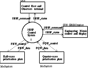
Figure 1. Context Diagram; ISIS Polarisation Control System.
Data dictionary entries for the context diagram are :-
ISISP_command = PHW_command + PQW_command
ISISP_status = PHW_status + PQW_status
The context diagram in figure 1 shows the ISISP control system software as a single process bubble with data flows to or from external terminators which are not part of the system being described. The control host and observer's terminal terminator has the same input and output flows as the engineering mimic control and display terminator. The input flow ISISP_status consists of three types of status information:-
z The status of the ISIS polarisation mechanisms.
z The command validation status, used to report the status returned after a command has been received and its value and parameters have been checked.
z The command response status, used to monitor the progress of a mechanism command.
The output flow ISISP_command includes all commands directly translatable into ADAM actions used by either the observer or an engineering user to control the ISIS polarisation module. The terminators half-wave polarisation plate and quarter-wave polarisation plate have directly equivalent input and output flows. The input flows PHW_control and PQW_control are the hardware commands used to set up and control the mechanisms. The output flows PHW_data and PQW_data represent the hardware status of the mechanisms.
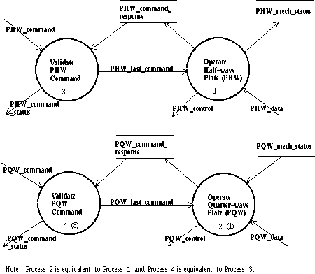
Figure 2. DFD 0; ISISP Control System.
Data dictionary entries for DFD 0 are:-
PHW_last_command = slide_command + angle_command + rotate_command
PHW_control = slide_control + angle_control + rotate_control
PHW_data = slide_position + angle + rotation_index
PHW_mech_status = slide_status + angle_status + rotate_status
PHW_status = PHW_mech_status + PHW_command_status + PHW_command_response
These data dictionary entries are equivalent for processes 2 and 4.
DFD 0, the top-level data flow diagram in figure 2, shows the ISISP control system software broken down into four processes. The individual processing bubbles on the diagram are as follows:-
Process 3, Validate PHW command has the input flows PHW_command which is the set of all commands used to control the half-wave polarisation plate; and PHW_command_response which is used to monitor the progress of half-wave plate commands. The output flow PHW_last_command is the set of all validated commands used to control the half-wave polarisation plate. Process 3 checks the value and parameters of commands, returns the command validation status and outputs the validated command to Process 1.
Process 1, Operate Half-wave Plate (PHW) has input flows PHW_last_command and PHW_data. PHW_last_command is the set of validated commands used to control the half-wave plate; and PHW_data represents the hardware status of the half-wave plate. The output flows are PHW_command_response, PHW_control and PHW_mech_status. PHW_command_response provides action information on the progress of a command; PHW_control consists of the commands to set up and control the hardware; and PHW_mech_status is the hardware status of the half-wave plate sub_mechanisms slide, angle and rotate.
Processes 2 and 4 are equivalent to processes 1 and 3 respectively.
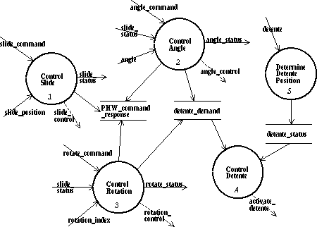
Figure 3. DFD 1; Operate Half-wave Plate (PHW).
Data dictionary entries for DFD 1 are:-
angle_command = [angle_move + angle_demand | angle_datum
rotate_command = [rotate_move + rotate_demand | rotate_stop]
rotate_control= [activate_rotation | stop_rotation]
slide_command = [slide_move + slide_demand | slide_datum]
slide_position = slide_in + slide_out
Figure 3, DFD 1 shows the operation of the half-wave polarisation plate broken down into five processes. Three of these processes are concerned with control of the three sub-mechanisms of the half-wave plate. The remaining two processes are the monitoring and control of the detente arm, a mechanism introduced to satisfy user requirement 1.51.
Process 1.1 Control Slide has input flows slide_command and slide_position. Slide_command is the set of commands used to control the slide sub-mechanism and slide_position is the hardware status of the slide sub-mechanism. The output flows are slide_status, PHW_command_response and slide_control. Slide_status is the hardware status of the slide sub-mechanism and slide_control consists of the commands used to set up and control the slide sub-mechanism hardware. PHW_command_response has been defined earlier
Process 1.2 Control Angle has input flows angle_command, slide_status and angle. Angle_command is the set of commands used to control the angle sub-mechanism; angle is the value of the angular encoder; and slide_status has been defined earlier. Output flows are PHW_command_response (previously defined), detente_demand, angle_control and angle_status. Detente_demand is the requested position of the detente mechanism. Angle_control consists of the commands used to set up and control the angle sub-mechanism hardware; and angle_status is the angular position of the angle sub-mechanism together with any error/health messages. Process 1.2 has control of the detente mechanism in order to clamp critical target angles or unclamp the wave-plate when a new angle is requested.
Process 1.3 Control Rotation has input flows rotate_command, slide_status and rotation_index. Rotate_command is the set of commands used to control the rotate sub-mechanism; rotation_index is a hardware signal indicating completion of one revolution; and slide_status has been defined previously. The output flows are PHW_command response and detente_demand, both previously defined; and rotate_status and rotation_control. Rotate_status is the rotation speed of the waveplate together with any error/health messages; and rotation_control consists of the commands used to set up and control the rotation sub-mechanism. Process 1.3 has control of the detente mechanism so that the wave-plate can be unclamped before initiating rotation of the waveplate, thus preventing mechanical damage.
Process 1.4 Control Detente has input flows detente_demand and detente_status. Detente_demand is the requested position of the detente arm; detente_status is the actual position of the detente arm. The output flow is activate_detente, which is a hardware command used to control the detente mechanism. Process 1.4 activates the detente whenever the detente status is not equal to the detente_demand.
Process 1.5 Determine Detente Position has input flow detente, which is the value of the.hardware switch used to detect the position of the detente arm. The output flow is detente_status. Process 1.5 reads the detente status switch and stores the result in detente_status.
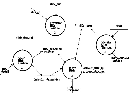
Figure 4. DFD 1.1; Control Slide.
Data dictionary entry for DFD 1.1:-
slide_command = [activate_slide_in | activate_slide_out]
DFD 1.1 shown in figure 4 breaks the control of the slide sub-mechanism down into four processes.
Process 1.1.1 Select Slide Position has two input flows slide_demand and slide_datum. Slide_demand is a parameter to the command slide_move indicating desired position. Slide_datum is one of two valid commands used to control the slide sub-mechanism. This command instructs the slide sub-mechanism to move to the datum position and requires no parameter as the desired position is implicit in the command. The output flows are slide_command_response and desired_slide_position. Slide_command_response provides action information on the progress of a command to the slide sub-mechanism. Desired_slide_position is the target position requested by a command to the slide sub-mechanism. Process 1.1.1 outputs desired_slide_position and sets slide_command_response to ACTIVE. If slide_datum is present then desired_slide_position will be equal to slide_datum_position otherwise desired_slide_position will be equal to slide_demand.
Process 1.1.2 Determine Slide Position has two input flows, slide_in and slide_out which are the hardware values of the slide position switches. The output flow is slide_status which contains the position status of the slide together with any appropriate error/health messages.
Process 1.1.3 Move Slide has input flows slide_status, desired_slide_position and slide_command. These input flows have been described previously. The output flows are slide_command_response (defined earlier), activate_slide_in and activate_slide_out. Activate_slide_in and activate_slide_out are hardware commands controlling the two slide solenoids. Process 1.1.3 activates the relevant slide solenoid until the desired position has been reached only if a slide_datum or slide_move control signal has been received; and sets slide_command_response to DONE.
Process 1.1.4 Monitor Slide Timeout has input flows slide_command_response and clock. The output flow is slide_status. Process 1.1.4 monitors the elapsed time from slide_command_response being set to ACTIVE and outputs a timeout error message to slide_status if the slide command is not completed within a predetermined time.
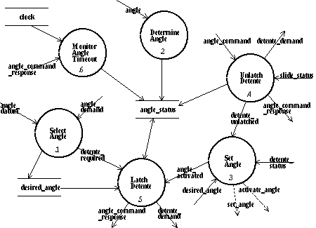
Figure 5. DFD 1.2; Control Angle.
Data dictionary entry for DFD1.2 is as follows:-
angle_command = activate_angle + set_angle
Figure 5 shows DFD 1.2 which decomposes the control of the angle sub-mechanism into 6 processes.
Process 1.2.1 Select Angle has input flows angle_demand and angle_datum. Angle_demand is a parameter to the command angle_move indicating desired angular setting. Angle_datum is one of two valid commands used to control the angle sub-mechanism. This command instructs the angle sub-mechanism to move to the datum angular setting and requires no parameter as the desired setting is implicit in the command. Output flows are desired_angle and detente_required. Desired_angle is the target angular setting requested by a command to the angle sub-mechanism. Detente_required is a message indicating that the detente mechanism is required. Process 1.2.1 outputs the desired_angle. If angle_datum is present then desired_angle will be equal to angle_datum_position, otherwise desired_angle will be equal to angle_demand. This function also calculates whether the detente is required and outputs the result. A detente is only required for 16 critical target angles.
Process 1.2.2 Determine Angle has input flow angle which is the value of the angular encoder. The output flow is angle_status which contains the angular setting status of the waveplate together with any appropriate error/health messages. Process 1.2.2 reads in angular encoder information and stores this data in angle_status.
Process 1.2.4 Unlatch Detente has input flows angle_command which is the set of commands used to control the angle sub-mechanism; and slide_status The output flows are angle_command_response, detente_demand and detente_unlatched. Angle_command_response provides action information on the progress of a command to the angle sub-mechanism. Detente_demand is the requested position of the detente mechanism, and detente_unlatched is a message indicating that a request to unlatch the detente has been issued. Process 1.2.4 outputs a detente_demand signal and a detente_unlatched signal when either an angle_datum or angle_move signal is received. The purpose of this function is to unlatch the detente before the wave-plate is moved to a new angular position, and to set angle_command_response to ACTIVE.
Process 1.2.3 Set Angle has input flows detente_unlatched, detente_status and desired_angle all of which have been defined previously. Output flows are angle_status (described earlier), angle_activated, set_angle and activate_angle. Angle_activated is a message indicating that the angle sub-mechanism hardware has been activated. Set_angle and activate_angle are hardware commands setting up and initiating the hardware respectively. Process 1.2.3 activates the hardware to move the wave-plate to the desired angle provided that a detente_unlatched signal has been received and the detente_status indicates that the detente has been successfully unlatched. If these conditions have been met and the wave-plate angle sub-mechanism is activated then an angle_activated signal is output.
Process 1.2.5 Latch Detente has input flows angle_activated, angle_status, desired_angle and detente_required. The output flows are angle_status, angle_command_response and detente_demand. The input and output flows have all been described previously. Process 1.2.5 outputs a detente_demand signal once an angle_activated signal has been received, provided that a detente_required signal is present and that the angle_status is equal to the desired_angle. This process also sets angle_command_response to DONE.
Process 1.2.6 Monitor Angle Timeout has input flows clock and angle_command_response. The output flow is angle_status. Process 1.2.6 monitors the elapsed time from angle_command_response being set to ACTIVE and outputs a timeout error message to angle_status if the angle command is not completed within a predetermined time.
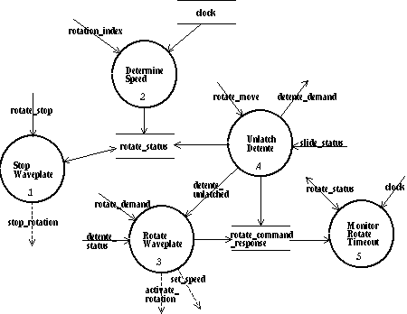
Figure 6. DFD 1.3; Control Rotation.
Data dictionary entry for DFD 1.3 is :-
rotate_command = [activate_rotation + set_speed | stop_rotation]
DFD 1.3 is shown in figure 6. In this figure the control of the rotation sub-mechanism has been broken into 5 processes.
Process 1.3.1 Stop Waveplate has input flow rotate_stop which is one of two valid commands used to control the rotate sub-mechanism. The output flow is stop_rotation which is a hardware command used to halt rotation of the waveplate. Process 1.3.1 outputs a stop_rotation signal to the hardware if a rotate_stop signal has been received and if the speed of rotation is greater than zero.
Process 1.3.2 Determine Speed has input flows rotation_index and clock. The output flow is rotation_status which contains the waveplate rotation speed together with any appropriate error/health messages. Process 1.3.2 reads in a rotation_index which together with a clock signal is used to calculate speed of rotation of the waveplate in Hz.
Process 1.3.4 Unlatch Detente has input flows rotate_move and slide_status. Rotate_move is a command used to control the rotate sub-mechanism and the slide_status is the position of the slide mechanism. The output flows are detente_demand, rotate_status, detente_unlatched and rotate_command_response. Process 1.3.4 outputs a detente_demand signal and a detente_unlatched signal when a rotate_move signal is received, provided that the slide position is in beam. The purpose of this function is to unlatch the detente before the wave-plate is rotated continuously, and to set rotate_command_response to ACTIVE.
Process 1.3.3 Rotate Waveplate has input flows detente_unlatched, rotate_demand and detente_status. Rotate_demand is a parameter to the command rotate_move indicating desired speed of rotation. The output flows are rotate_status, rotate_command_response, set_speed and activate_rotation. Rotate_command_response provides action information on the progress of a command to the rotate sub-mechanism. Set_speed and activate_rotation are hardware commands controlling the rotate sub-mechanism. Process 1.3.3 initiates rotation of the waveplate by outputting an activate_rotation signal provided that a detente_unlatched signal has been received and the detente_status indicates that the detente has been successfully unlatched.
Process 1.3.5 Monitor Rotate Timeout has input flows rotate_command_response, rotate_status and clock. The output flow is rotate_status. Process 1.3.5 monitors the elapsed time from rotate_command_response being set to ACTIVE and outputs a timeout error message to rotate_status if the requested rotation speed is not achieved within a predetermined time.
Requirement 1: The system will provide the same functionality for both the half-wave polarisation plate and the quarter-wave polarisation plate.
Requirement 2: The system will move the wave plate slides in and out of the beam.
Requirement 3: The system shall provide status information on the wave-plate slides positions.
Requirement 4: The system will move the wave-plates to any demanded angle between 0 and 359.9 degrees with a resolution of 0.1 degrees to an accuracy of 0.2 degrees. If the demand angle is critical (i.e. a multiple of 22.5 degrees) then the wave-plate will be clamped in position using a detente mechanism to an accuracy of 0.1 degrees.
Requirement 5: The system shall provide status information on the angular position of the waveplates.
Requirement 6: The system will rotate the waveplates at any demanded speed between 0.1 and 1 Hz with a resolution of 0.1 Hz.
Requirement 7: The system will stop the waveplates rotating.
Requirement 8: The system shall provide status information on the rotational speed of the waveplates.
3.2 Interface requirements
Requirement 9: The system shall communicate with the control host and an engineering mimic via a TCP/IP ethernet connection using EPICS channel access.
Requirement 10: The system shall use the ADAM messaging system as its control interface.
3.3 Operational requirements
Requirement 11: The system shall be run from either the operator's terminal or an engineering mimic.
Requirement 12: The system will operate the half-wave and quarter-wave polarisation plates independently of each other.
Requirement 13: The system shall make available to both the operator`s terminal and an engineering mimic all status information regarding the polarisation module.
3.4 Resource requirements
Requirement 14: The system shall be written using EPICS and any EPICS tools.
Requirement 15: The system shall use the VxWorks real-time operating system.
3.5 Verification requirements
Requirement 16: The system shall allow simulation of the commands generated by the ADAM I-task.
3.6 Documentation requirements
Requirement 17: The documentation shall include a full description of the system design; a user manual; and a maintenance manual including fault-finding and repair information.
Requirement 18: All documentation shall be supplied in hard copy and wherever possible in electronic format.
3.7 Security requirements
Requirement 19: The system shall be inaccessible to users not authorised by Operations staff.
Requirement 20: Write access to the system software shall be reserved to Operations staff.
3.8 Quality requirements
Requirement 21: The system software shall be written in accordance with an RGO-approved subset of the ESA software engineering standards ESA PSS-05-0 Issue 2.
3.9 Reliability requirements
Requirement 22: The minimum time between severe failures shall be in excess of three weeks.
3.10 Maintainability requirements
Requirement 23: The MTTR (Mean Time To Repair) shall be no longer than 30 minutes.
Requirement 24: The software shall be structured in such a way to allow future modifications of the software to control all ISIS mechanisms.
3.11 Safety requirements
Requirement 25: Where the system has control of a moving mechanism safeguards shall be built in to prevent mechanical damage.
Appendix A. Requirements traceability matrix
The following table relates the user requirements as described in document WHT-ISIS-4 to the software requirements described in this document.


Appendix B. Document history
Issue 1.1 24/08/95 First issue.