Requirement for Software Test Mode
To be able to test the instrument it is necessary to simulate inputs to the EPICS system. This may be done at the hardware side by the injection of a suitable voltage to the hardware card. This will test that the hardware/software interface is functioning correctly. If a suitable test box is not available or it is only necessary to test the software then the system has been designed to allow this by switching to a "Software Test Mode" state.
Setting the Test Mode
Each instrument should have a process variable (PV) with the name <instrument>:common:test
The test mode can be set by changing this PV value to a NONE ZERO value. For example by using caput from a command line:-
epicssm@taurus% caput test:common:test.VAL 1
Old : test:common:test.VAL 0
New : test:common:test.VAL 1
WARNING This will disconnect the currently read value from the hardware device.
To indicate that the system is in Software Test Mode the Engineering GUI's that have PV's that are affected by this will display the necessary information. For example the "about" GUI for the test system used for USP development shows the following state:-
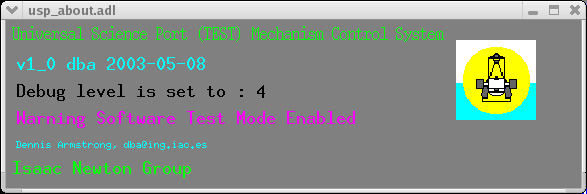
The GUI displays the message "Warning Software Test Mode Enabled" in the colour purple.
It can be reset by changing this PV value to a ZERO value. For example by using caput from a command line:-
epicssm@taurus% caput test:common:test.VAL 0
Old : test:common:test.VAL 1
New : test:common:test.VAL 0
This feature will allow an automatic test script to be run for testing of the instrument.
Note that any Engineering GUI that has a PV which can be set into "Software Test Mode" will display a purple box around this displayed value as shown below.
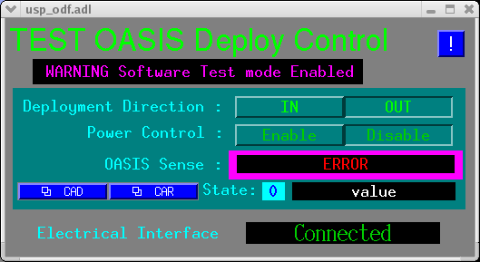
The PV which is affected in this GUI is test:odf:sense.VAL currently displaying ERROR.
To set values into the PV the SVAL field is used to set the software value.For example by using caput from a command line:-
epicssm@taurus% caput test:odf:sense.SVAL 2
Old : test:odf:sense.SVAL 0
New : test:odf:sense.SVAL 2
This will cause the PV test:odf:sense.VAL to contain the value 2 which will display as
"IN" on the GUI.
A further example by using caput from a command line:-
epicssm@taurus% caput test:odf:sense.SVAL 1
Old : test:odf:sense.SVAL 2
New : test:odf:sense.SVAL 1
This will cause the PV test:odf:sense.VAL to contain the value 1 which will display as
"OUT" on the GUI.
How Its Done
For each PV that requires to be simulated the following fields are set in the PV:-
SIML:DB_LINK <instrument>:common:test.VAL NPP NMS
and
SIMM: YES
For example to simulate the input of the PV test:odf:sense :-
Use capfast or a suitable editor to change the database fields as required.
Debugging EPICS applications
Error messages can appear either on the EPICS console or sent to the error log and viewed in the "talker window". The verbosity of these error messages may be controlled.
Each instrument should have a process variable (PV) with the name <instrument>:common:debuglvl
The debug level can be set by changing this PV value to a NONE ZERO value. For example by using caput from a command line:-
epicssm@taurus% caput test:common:debuglvl.VAL 4
Old : test:common:test.VAL 0
New : test:common:test.VAL 4
Usually the greater this value the more verbose the error messages are. This is used for debugging of the instrument application
Each application like the motorApp also has variables for debugging purposes for example the motorApp has several:-
- recMotordebug
- devOMSdebug
- drvOMSdebug
Setting these variables to a NONE ZERO value will cause debugging messages to appear on the EPICS console.
These are VERY verbose error messages.