

Previous: Overview
Up: Overview
Next: Performance
Previous Page: Overview
Next Page: Performance


Previous: Overview
Up: Overview
Next: Performance
Previous Page: Overview
Next Page: Performance
The layout of the IDS spectrograph is shown in Figure 3.1. The following components can be discerned:
 m (0.216 arcsec) to 1.745 mm
(9.43 arcsec) in steps of 5
  m (0.027 arcsec). The entire slit
assembly can be removed, if required. Dekker plates are interchangeable
in sets; each individual set consisting of 8 apertures and a clear
position. Several standard dekkers, incorporating
single slots, pairs of slots, a ``comb'', and a coronographic set-up, are
always available.
A multislit unit is also available. This consists of ten parallel
slitlets, each 16s long with a 7s gap between each pair and with
a fixed width of 270  m (1.46s at the Cassegrain focus). Each
slit can be moved perpendicular to the slit orientation by up to
1.6
  in either direction. With FOS-1 a useful field of
4
  by 3
by 3  can be covered, whereas the IDS has a smaller field
of 4
  by 1
by 1  . A program is available for finding the optimum
arrangement and typically one needs 20 or 30 objects in the field to make use
of all 10 slits. Astrometry to within 0.3s is needed to use the unit
effectively. There is only one module that has to be preset using
a Coradograph xy table in the INT building. Clusters of objects spread
over less than 1
  are less likely to benefit as they are too small.
To install the multislit assembly, the
conventional Cass cluster slit assembly is replaced by a similar one
which holds the multislit module or a long-slit equivalent. This instrument
change requires lowering the IDS and is a daytime operation. The long slit
module allows observations to continue while the multislit module is being
preset with the Coradograph for a new field. The device should not be regarded
as a general purpose multiobject coupler but rather as a special purpose
addition to the INT Cassegrain cluster instrumentation.
See Using the multislit unit at the
INT Cassegrain focus (R. Ellis et al. 1986) for more information.
 60 mm
60 mm  2 mm and made from Schott glass. The
wavelength dependence of the
transmission of these filters is shown in figures 2.5 and 2.6. The copper
sulphate filter cuts out the part of the spectrum from 600 - 650 nm
redwards and is usually employed to block the red leak of the UG11 filter
or to remove the FOS-1 first order.
The neutral density filters
below the slit provide a choice of ND = 0.5, 1.0 and 1.5.
Note that the use of filters below the slit makes it necessary to
refocus the spectrograph.
Along the direction of the slit (i.e. perpendicular to the dispersion
direction), the focal lengths of 235 and 500 mm imply slit to detector
reduction factors of 5.43 and 2.55 respectively, and hence scales
at the detector of 29.4 and 13.8 arcsec mm .
.
Along the dispersion direction, the slit to detector reduction factor
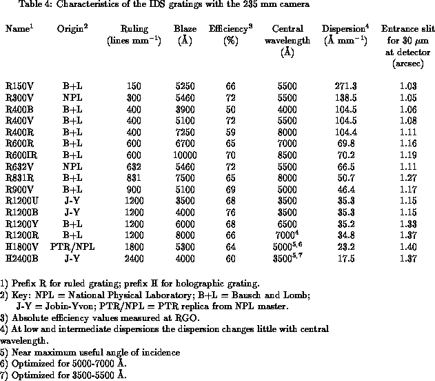
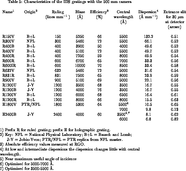
is more complicated, since it depends on the grating angle. Tables 3.1
and 3.2 give the slit width in arcsec which projects to 30  m at the
detector, when each grating is used at its central wavelength.
Tables 3.1 and 3.2 also list the dispersion provided by each grating and
camera combination. It can be seen that a wide range of dispersions
is available, from 7 Å mm to 270 Å mm
 .
.


 128 mm. A wide selection is available,
and some of the important characteristics of each grating are summarised
in Tables 3.1 and 3.2. The efficiency of the gratings as a function of
wavelength is shown in Figure 2.4. Grating changes can be made during
the night by support staff.
 and
blazed at 4800 Å, can be inserted into the collimated beam in the
235 mm camera to provide a cross-dispersion option. This is
used in conjunction with an R150 echelle grating, which is blazed at
2.7
  m. The FOS-1 dekker mask is used to limit the slitlength to 25
arcsec in order to avoid order confusion.
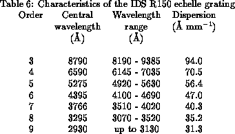
The wavelength range for the CCD and dispersion provided by this grating in
each order, for a grating angle of 60
  , are summarised in Table 3.3. There
are no gaps in wavelength coverage with the IPCS.
The CCD is not normally considered the detector best suited to use with the
cross-disperser, because part of the wavelength coverage is lost between
the orders due to the physical size of the chip. However, it is usually
possible to adjust the grating angle in the range 59.5
  - 60.5
  so as to
ensure that all interesting spectral features are placed in the chip.
Besides the
advantages typical of CCDs, the combination of GEC chip and cross-disperser,
seems to have a higher sensitivity than the combination of
IPCS and cross-disperser. 13 counts/sec/Å were obtained for a
m
 =11.9 star at an airmass of 1.32 with the CCD. 1 count/sec/Å
therefore, can be expected for a m
 =14.8 at an airmass of 1.0. This count
rate corresponds to a m
 =13.9 with the IPCS, but of course the IPCS's
quantum efficiency is much lower at 5500 Å than that of the CCD.
The central wavelength and wavelength coverage in Å can be obtained for
each order
  as
as
 and
and


 around the optical
axis (or exchanged), and the control software to be reinitialized. Note that if
you only specify a detector to be on one camera in your proposal, you cannot
guarantee what will be on the other (e.g. it might be in use on another
telescope). If you need both cameras, you have to specify that well before
your run.


