| THE ING NEWSLETTER | No. 3, September 2000 |
|
|
SCIENCE |
|
|
|
| Previous: | NAOMI Progress | Up: | Table of Contents | Next: | INTEGRAL: A Simple and Friendly Integral Field Unit |
Other available formats: PDF | gzipped Postscript
S-Cam Update Novel Capabilities for Resolving Old Problems !
Nicola Rando (ESA) and Peter Moore (ING)
In a previous article in this newsletter (ING Newsletter, No. 1, p. 13) we presented the novel Superconducting Tunnel Junction detector (STJ). A novel technological advance ready to open up the skies for new discoveries. Since then much work has been done by the team at ESA to improve S-Cam and the third run of this camera has been successfully completed.
The main changes in S-Cam 2 concern the increased resolving power (now of order 8 at 500 nm), the higher maximum count-rate sustained by each of the electronics channels (now equal to 5 kHz), a simplified setup and alignment procedure and a number of improvements in the Graphical User Interface software. The camera design is based on a bottom loading 4He cryostat hosting an adsorption 3He cooler. A dedicated optical collimator unit interfaces the camera focal plane to the Nasmyth focus of the Ground High Resolution Imaging Laboratory (GHRIL) of the WHT.
A plate scale of 0.6 arcsec/pixel was selected to match the telescope point spread function (typically around 1 arcsec). The optical unit is based on a reflective section and on a lens objective. Two filter wheels are available with neutral density and narrow band filters. The front-end electronics is based on 36 charge sensitive preamplifiers and related shaping stages working at room temperature: these allow to individually bias and read-out each STJ of the array. Optimised shaping stage filters allow to maximise the signal to noise ratio without penalising the count-rate capability of the electronics (now increased to 5 kHz/channel). Each channel has a peak detection unit and an analog to digital converter which allow us to perform pulse height analysis on each detected photon. Every event is then associated with a highly accurate time of arrival provided by a commercial Global Positioning System receiver. The electronics system is controlled via a dedicated data acquisition computer, which is then interfaced with a remote control PC. Such a control PC functions as Graphical User Interface and allows the remote control of the main instrument functions (from the telescope control room), including the array operating parameters. The data storage takes place on the same unit, which also provides some limited data analysis capability (data 'quick-look' functions).
As a consequence of the high detector
responsivity and detection efficiency, the rejection of thermal infrared
photons is crucial for the camera performance, directly influencing the
resolving power of the instrument. While the expected sky background flux
at the Nasmyth focus does not represent a major problem (with an expected
integral number of counts of order 50 counts per second, per pixel), the
thermal radiation emitted by warm parts in the field of view of the array
would affect the system performance. In order to minimise this degradation
mechanism, adequate IR filters must be used. In this latest configuration,
S-Cam 2 adopts two KG2 glass filters of different thickness, cooled at
a temperature of 12 and 2 K respectively. A third silica element is located
in front of the focal plane array and maintained at 0.32 K. The optical
entrance window of the cryostat is sapphire, with standard ARC's on one
side and a multi-layer IR filter on the opposite side. Mainly due to the
presence of these filters, the overall camera throughput in the nominal
band-pass is of order 25%. Further development work is ongoing in order
to improve the efficiency of the IR filters.
| S-Cam 2 Characteristics
Band-pass: 350 650nm (at 10% photon collection efficiency) Provided data per detected event: Wavelength, arrival time, pixel identification Resolving power ( Event time accuracy: 5 µsec (absolute time reference via GPS) Maximum count rate: 5 kHz/pixel Camera field of view: 4.0 × 4.0 arcsec2 (plate scale = 0.6 arcsec/pixel) Instrument installation: Nasmyth focus (f/11) William Herschel Telescope Observation time: In excess of 10 hours (cooler hold time) Camera focus adjustment: Via telescope secondary mirror and dedicated optical unit Camera guiding: Auto-guider Filter wheel: 2 sets of 8 filters on 2 independent wheels On-line data analysis: 'Quick-view' software installed on control PC Data storage format: FITS format (via control PC) |
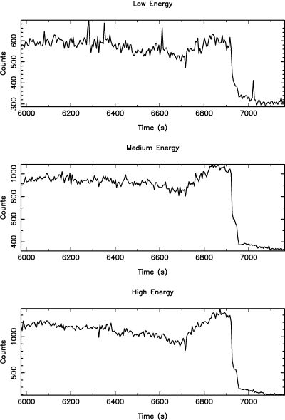
In December 1999 and April 2000 a series of astronomical demonstration campaigns were completed at the WHT focusing on the astronomical exploitation of the camera rather than on engineering aspects. The campaigns demonstrated stable operations from all the 36 elements of the array and a performance level fully equivalent to what was recorded in the laboratory during the integrated system testing. One of the first astronomical objects observed during these campaigns was UZ For, one of a class of short-period binary systems known as polars or AM Her stars. The two stars which constitute this binary system are very different: a low-mass dwarf star cooler than our sun but which is still burning hydrogen in its core, and a much smaller stellar remnant known as a white dwarf. White dwarfs, the evolutionary end-point of a sun-like star, typically contain about as much mass as our own sun, but squeezed into a volume about the size of the Earth. In the case of polars, they are also highly magnetised, with surface magnetic field strengths ranging from 10 to 70 MG. The two stars are so close that they may orbit around each other in only a few hours, with matter being drawn off the ordinary dwarf star onto the surface of the white dwarf, giving off X-rays in the process. The white dwarf rotates synchronously with the binary period and its strong magnetic field prevents the in-falling matter from forming an accretion disk. Such systems are ideal candidates for study with S-Cam since they display a rich variety of spectral and temporal variations in the optical, due to the emission, absorption and occultation effects of the various system components: the dwarf star, accretion stream, and hotspot. While this makes them interesting from an astrophysical point of view, the requirement to combine high time-resolution with medium resolution spectroscopy has made them difficult to study using traditional dispersion spectroscopy/ CCD techniques. S-Cam's combination of energy sensitivity and millisecond timing capability plus its exceptional detection efficiency make it highly suited to the study of these binaries. Figure 1 shows an S-Cam observation of the eclipse transition of this 127 minute binary UZ For in three energy bands (low, medium and upper). The energy bands were defined by dividing the full energy range into three bands (i.e. wavelength) intervals. The low energy band extends from 1800 nm to 620 nm; the medium energy band extends from 620 nm to 525 nm and the high energy band from 525 nm to 215 nm. It should be noted that the S-Cam photon collection efficiency at wavelengths longer than 750 nm and shorter than 325 nm is below 1%, while it peaks at 525nm, just above 25%. The data, provided by all the pixels of the array, have been rebinned into 3 second time intervals for the sake of clarity. The eclipse corresponds to the white dwarf passing behind the normal dwarf star, which itself contributes very little light. The extremely sharp eclipse transition demonstrates that most of the emission is coming from a hotspot on the surface of the white dwarf. Just after the onset of the eclipse, a ledge-like structure is seen in the light curve that persists for a few seconds before falling off less sharply; this is probably the contribution from the white dwarf's photosphere.
 |
|
|
In conclusion, the capability to provide simultaneously imaging, arrival time and spectro-photometric information make Superconducting Tunnel Junctions a good candidate for the next generation of detectors for optical astronomy. Ta-Al based devices have demonstrated single photon counting capability at wavelengths longer than 2 µm and responsivity ranging from 104 to 105 e/eV at an operating temperature of 0.3 0.5 K. On this basis, 6×6 Ta arrays with 25×25 µm2 pixels have been fabricated and successfully operated in the visible, UV and X-ray regime, showing uniform performance and demonstrating the possibility to perform multichannel operations. The detectors do not have any significant cross-talk between adjacent pixels, while the Josephson current of the pixels can be satisfactory minimised at a common magnetic field intensity.
The instrument has now demonstrated its capability of producing astronomically relevant data. The typical camera applications capitalise on the specific characteristics of Superconducting Tunnel Junction detectors, with particular emphasis on the time resolution and simultaneous spectro-photometric capabilities (e.g. study of time variable objects, such as pulsars and binary systems). Despite the presently limited FOV and the modest spectral resolution, S-Cam 2 has provided valuable astronomical results during a series of observations conducted at the WHT.
The camera design has continued to evolve in parallel with the detector array development, with particular regard to larger array formats and innovative read-out schemes, allowing a significant enlargement of the related FOV. While larger format arrays can be produced within the limits of the present fabrication technology, the current front-end approach may require significant changes in order to read-out in excess of 10×10 elements. Parallel development activities are ongoing in order to determine alternative read-out schemes, thus opening the way to considerably larger format arrays. Additional development work is underway in order to improve further the wavelength resolving power by using more effective IR filters and/or by modifying their configuration inside the cryostat. In addition, the migration to lower energy-gap superconductors, with a commensurate increase in resolving power is now under study. Finally, a considerable effort is being invested in simplifying the instrument operations, by limiting the need for cryogenic liquids and by adopting innovative cryogenic technologies. Such changes will allow the operation of future generations of this type of camera at remote observation sites as common user facilities.
Further information on STJ detectors and S-Cam can be found at the following URLs:
http://astro.estec.esa.nl/SA-general/Research/Stj/STJ_main.html
http://astro.estec.esa.nl/SA-general/Astronews/37-html/an37.html#stj
ftp://astro.estec.esa.nl/pub/sciproj/dmartin_ltd8.pdf
We acknowledge the key contribution
of other members of the Astrophysics Division of ESA, at ESTEC. In particular
J. Verveer and S. Andersson who provided engineering support during the
instrument development and at the telescope, and P. Verhoeve and T. Peacock
for the optimisation of the detector performance and its detailed evaluation.
The astronomical observations performed with S-Cam and the data interpretation
have been carried out by F. Favata and M. A. C. Perryman, supported by
A. Reynolds.
Email contact: Peter Moore (pcm@ing.iac.es)
| Previous: | NAOMI Progress | Up: | Table of Contents | Next: | INTEGRAL: A Simple and Friendly Integral Field Unit |
| GENERAL | SCIENCE | TELESCOPES AND INSTRUMENTATION | OTHER NEWS FROM ING | TELESCOPE TIME |