


Previous: Return beam from slit to CCD autoguider
Up: A&G unit design
Next: Beam from calibration unit to spectrograph
Previous Page: Return beam from slit to CCD autoguider
Next Page: Beam from calibration unit to spectrograph
Previous: Return beam from slit to CCD autoguider
Up: A&G unit design
Next: Beam from calibration unit to spectrograph
Previous Page: Return beam from slit to CCD autoguider
Next Page: Beam from calibration unit to spectrograph

The slitviewer fibre image guide gives only a very small field of view. This is adequate for verifying that the object remains on the slit during an exposure, but is not adequate for target acquisition. An additional means of viewing the entire field at a very coarse scale on an acquisition TV is therefore provided. The scale is about 1.14 arcsec/pixel in the X direction on the TV, and about 0.73 arcsec/pixel in the Y direction. This option cannot be used whilst an exposure is active.
In order to use the acquisition TV to view the field, it is neccesary to do three things:
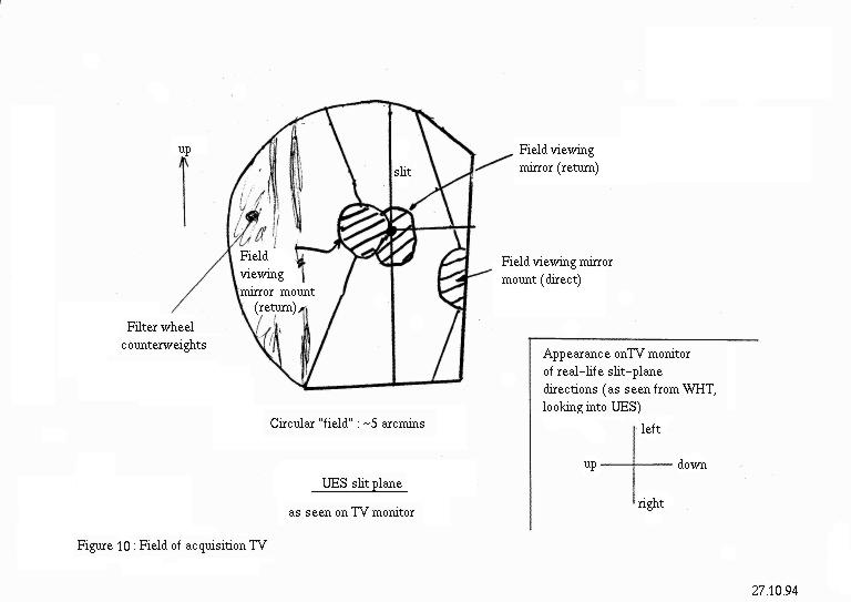
Even once these actions have been carried out, the field of view of the TV will still be obstructed; the slit-viewing probe obstructs both the beam from the telescope to the slit, and the return beam from the slit to the pickoff mirror. Fig. 10 is a sketch of the TV field, showing the following features:

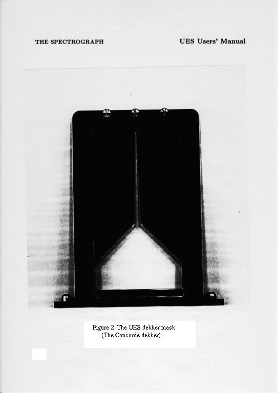
In order to use the TV to view the slitjaws, it is first necessary to move the dekker mask out of the way, by moving it to close to the top end of its range of movement.
Since the central part of the TV field is obstructed, it is
not possible to use the TV to centre an object on the slit directly.
After pointing the telescope at a new object, the normal
procedure is to apply a standard aperture offset. This will offset
the telescope so that the object appears in an unobstructed part
of the TV field. The object can be centred up, and the
aperture offset then removed to place the object back on the slit.
