


Previous: The need for a derotator
Up: The Derotation Optics
Next: Specification
Previous Page: The need for a derotator
Next Page: Specification
Previous: The need for a derotator
Up: The Derotation Optics
Next: Specification
Previous Page: The need for a derotator
Next Page: Specification
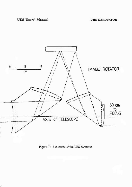
The image derotator is illustrated in Fig. 7. It consists of a flat mirror and a pair of fused silica prisms, each with lens surfaces. The detailed specification of the derotation optics is given in La Palma Technical Note 9.
The incoming beam from the telescope undergoes total internal reflection in the first prism, and emerges travelling in a direction close to perpendicular to the telescope axis. The beam is then reflected by the flat mirror back towards the second prism, where it again undergoes total internal reflection, and emerges travelling parallel to the telescope axis. The lens surfaces on the prisms extend the optical path, so that the position of the focal plane remains constant, and maintain good image quality.
The orientation of the output image is altered by rotating the whole assembly about the telescope axis. Rotating the derotation optics through a given angle has the effect of rotating the final image through twice that angle. Note that the derotation optics also has the effect of changing the image parity (i.e. the image field is mirrored as seen at the detector). In normal operation the unit is rotated by the telescope control system at an appropriate rate to keep the final image at a fixed orientation, the orientation required being specified by the observer.

