Previous: Detailed description of the search areas
Up: Detailed description of the search areas
Next: Algorithms
Previous Page: Detailed description of the search areas
Next Page: Algorithms

Definitions

Define the following variables:

F
The focal length (mm).
The sky position angle in radians.
The offset between the coordinate system of the guide probe and that of the instrument rotator, in radians.
The handedness of the guide-probe coordinate system (1).
x y
Guide probe coordinates, in encoder units.
x x y y
xy limits on the area within which guide stars may be selected, in encoder units.
r
Polar coordinates of the guide probe (encoder units; r is positive by definition).
r r
Limits on the area within which guide stars may be selected, in polar coordinates; encoder units).
e e
The linear and angular encoder scales in mm/encoder unit and rad/encoder unit, respectively.
x y
The position of the centre of rotation in encoder units in the guide probe coordinate system (used for xy systems only).
r
The radial offset for guide probe coordinates, in encoder units (used for r systems only).

All of the existing A&G boxes on the La Palma telescopes use xy stages for their guide probes, with the exception of the WHT Cassegrain system, which has an r arrangement. A general description of the search areas may be given as follows (note that not all configurations use every constraint):

  1. and (within a rectangle).
  2. or (within a circle: this may be either a result of vignetting or a restriction on the mechanical travel of the probe).
  3. (inner ellipse excluded). A minimum radial travel for an r system is a special case. A similar condition, or is used for the ROTATOR ANY option, where the available area is always a circular annulus.
  4. or or or ( i.e. the area and is excluded).
  5. The probe azimuth is in the range .

The current best estimates for these parameters are given in Tables 1 and 2 and the following description. These should be good enough to find guide stars, but accurate field calibrations are needed for all configurations. Note that the ``encoder scale'' quoted for the JKT f/8 configuration is not a bit size. The WFC guide probe is positioned manually and its location is read in mm.

Table 1(a): Limiting magnitudes, plate scales and encoder scales (xy systems)
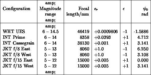
Table 1(b): Limiting magnitudes, plate scales and encoder scales (r systems)

Table 2(a): Guide probe offsets and limits (xy systems)
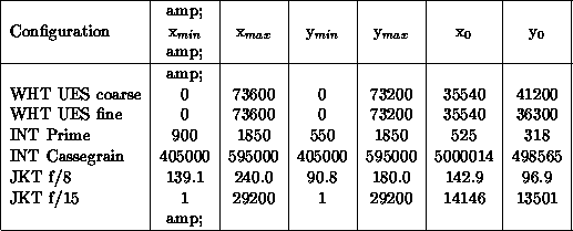
Table 2(b): Guide probe offsets and limits (r systems)


Previous: Detailed description of the search areas
Up: Detailed description of the search areas
Next: Algorithms
Previous Page: Detailed description of the search areas
Next Page: Algorithms

dxc@mail.ast.cam.ac.uk
Tue Apr 12 04:17:24 BST 1994